background image

GV58LAU User Manual


TRACGV58LAUUM001


– 

16 


4.


Troubleshooting and Safety Information 

4.1.


Troubleshooting 

Table 10: Solutions to Possible Trouble


Trouble 

Possible Reason 

Solution 

The CELL LED always flashes 

quickly after the device is 

turned on. 

The signal is too weak, and the 

device cannot be registered to 

the network. 

Please move the device to 

places with good GSM 

coverage. 

Messages cannot be reported 

to the backend server. 

The IP address or port of the 

backend server is wrong. 

Make sure the IP address 

for the backend server is an 

identified address on the 

Internet. 

Unable to power off the device. 

It is unable to power off the 

device if the charger is 

connected. 

Disconnect charger, and try 

again. 

The device cannot get 

successful GNSS fix. 

The GNSS signal is weak. 

Please move the device to a 

place with open sky. 

It is better to let the top 

surface (the surface with 

LED indicator) face the sky. 


4.2.


Safety Information 


Please do not disassemble the device by yourself. 


Please do not put the device on overheated or too humid place, and avoid exposure to direct 
sunlight. Too high temperature will damage the device or even cause battery explosion. 


Please do not use GV58LAU on the airplane or near medical equipment.   

Queclink  
Confidential

Summary of Contents for GV58LAU

Page 1: ...GV58LAU User Manual TRACGV58LAUUM001 0 GV58LAU User Manual GSM GPRS LTE Cat4 WCDMA GNSS Tracker TRACGV58LAUUM001 Version 1 00...

Page 2: ...ains the responsibility of the customer or the customer s system integrator All specifications supplied herein are subject to change Copyright This document contains proprietary technical information...

Page 3: ...7 2 3 LED Description 8 2 4 Power Connection 9 2 5 Ignition Detection 9 2 6 Digital Output 10 2 7 Digital Input Digital Output 11 3 Get Started 12 3 1 Parts List 12 3 2 GV58LAU External Cable Interfac...

Page 4: ...Abbreviations 6 Table 4 Description of 6 PIN Connections 8 Table 5 LED Description 8 Table 6 Electrical Characteristics of Ignition Detection 9 Table 7 Electrical Characteristics of Digital Output 10...

Page 5: ...Figure 4 Typical Ignition Detection 9 Figure 5 Digital Output Internal Drive Circuit 10 Figure 6 Typical Connection with Relay 10 Figure 7 Digital Input Digital Output Connection 11 Figure 8 Open the...

Page 6: ...GV58LAU User Manual TRACGV58LAUUM001 5 0 Revision History Version Date Author Description of Change 1 00 August 29 2022 Nancy Yin Initial Queclink Confidential...

Page 7: ...entation is provided for the full featured Track protocol The Track protocol supports a wide variety of reports including emergency alarm Geo fence boundary crossings external power supply monitoring...

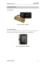
Page 8: ...1 Appearance of GV58LAU 2 2 Interface Definition GV58LAU has a 6 PIN interface connector It contains the connections for power and I O The sequence and definition of the 6 PIN connector are shown in t...

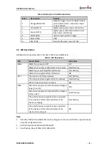
Page 9: ...age is below 3 65V Slow flashing The external power supply has been connected to the device and the internal battery of the device is charging Fast flashing The external power supply has been connecte...

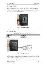
Page 10: ...gure 3 Typical Power Connection 2 5 Ignition Detection Table 6 Electrical Characteristics of Ignition Detection Logical State Electrical State Active 5 0V to 32V Inactive 0V to 3V or Open Figure 4 Typ...

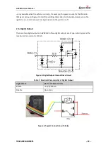
Page 11: ...n and enter power saving mode when the ignition is off There are two digital outputs on GV58LAU All two digital outputs are of open drain type and the maximum drain current is 150mA Figure 5 Digital O...

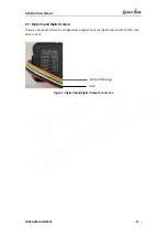
Page 12: ...11 2 7 Digital Input Digital Output There is one special I O can be configured as a digital input or a digital output with 150mA max drive current Figure 7 Digital Input Digital Output Connection IN1...

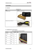
Page 13: ...Name Picture GV58LAU Locator 86 7mm 46 4mm 18 1mm Data_Cable_M_V4 Optional 3 2 GV58LAU External Cable Interface Table 9 GV58LAU User Cable Color Definition Definition Color PIN No Cable IN1 OUT3 Oran...

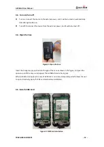
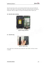
Page 14: ...urned off 3 4 Open the Case Figure 8 Open the Case Insert the triangular pry opener into the gap of the case as shown in the figure and push the opener up until the case is unsnapped The GV58LAU devic...

Page 15: ...der as shown above with the gold colored contact area facing down Take care to align the cut mark Close the SIM card holder Close the case 3 6 Install the Internal Battery Figure 10 Battery Installati...

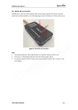
Page 16: ...The following figure shows the directions of the motion sensor Figure 12 Motion Sensor Direction Note 1 The opposite direction of the cable bundle is the positive direction of the X axis 2 The Z axis...

Page 17: ...nd server is an identified address on the Internet Unable to power off the device It is unable to power off the device if the charger is connected Disconnect charger and try again The device cannot ge...

Page 18: ...ature will damage the device or even cause battery explosion Please do not use GV58LAU 4 2 Safety Information Please do not disassemble the device by yourself Please do not put the device on overheate...

Reviews: