SC200L Hardware Design
SC200L_Hardware_Design
19 / 103
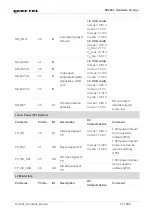
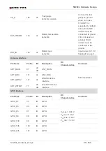
CSI1_LN1_P 68 AI
CAMERA MIPI data
1 signal (+)
CSI0_CLK_N 70
AI
CAMERA MIPI
clock signal (-)
CSI0_CLK_P 71
AI
CAMERA MIPI clock
signal (+)
CSI0_LN0_N 72
AI
CAMERA MIPI data
0 signal (-)
CSI0_LN0_P 73 AI
CAMERA MIPI data
0 signal (+)
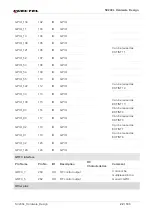
MCAM_MCLK
74
DO
Clock signal of
camera
V
OL
max = 0.20 V
V
OH
min = 1.46 V
1.85V power domain
SCAM_MCLK 75
DO
Clock signal of
camera
V
OL
max = 0.20 V
V
OH
min = 1.46 V
1.85V power domain
Can be used as
ordinary GPIO.
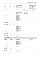
MCAM_RST 79 DO
Reset signal of
camera
V
OL
max = 0.20 V
V
OH
min = 1.46 V
MCAM_PWDN 80
DO
Power down signal
of camera
V
OL
max = 0.20 V
V
OH
min = 1.46 V
SCAM_RST 81 DO
Reset signal of
camera
V
OL
max = 0.20 V
V
OH
min = 1.46 V
SCAM_PWDN 82
DO
Power down signal
of camera
V
OL
max = 0.20 V
V
OH
min = 1.46 V
CAM_I2C_SCL 83
OD
I2C clock signal of
camera
CAM_I2C_SDA 84
OD
I2C data signal of
camera
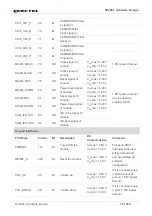
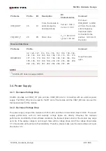
Keypad Interfaces
Pin Name
Pin No.
I/O
Description
DC
Characteristics
Comment
PWRKEY 114
DI
Turn on/off the
module
V
IL
max = 0.60 V
V
IH
min = 1.30 V
Pull-up to VBAT
internally.Active low.
RESET_N
225
DI
Reset the module
V
IL
max = 0.60 V
V
IH
min = 1.30 V
Off by default and
can be enabled via
software
configuration.
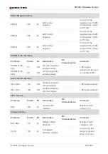
VOL_UP 95
DI
Volume
up
V
IL
max = 0.48 V
V
IH
min = 1.39 V
If it is not used, keep
it open.Cannot be
pull up. 1.85V power
domain
VOL_DOWN 96 DI
Volume
down
V
IL
max = 0.48 V
V
IH
min = 1.39 V
If it is not used, keep
it open.1.85V power
domain


