SC200L Hardware Design
SC200L_Hardware_Design
23 / 103
NOTES
1)
SC200L-WF does not support GNSS.
3.4. Power Supply
3.4.1. Decrease Voltage Drop
SC200L provides two VBAT_RF pins and two VBAT_BB pins for connecting with an external power
supply. The VBAT_RF pins are used for the RF part of the module and the VBAT_BB pins are used for
the baseband part of the module.
3.4.2. Decrease Voltage Drop
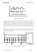
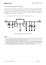
The power supply range of the module is 3.50V~4.20V, and the recommended value is 3.80V. The power
supply performance, such as load capacity, voltage ripple, etc. directly influences the module’s
performance and stability. Under ultimate conditions, the transient peak current of the module may surge
up to 3A. If the supply voltage is not enough, there will be voltage drops, and if the voltage drops below
3.1V, the module will be turned off automatically. Therefore, please make sure the input voltage will never
drop below 3.1V.
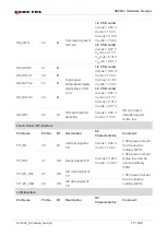
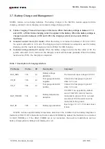
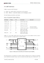
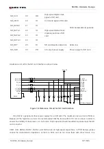
Pin Name
Pin No.
I/O
Description
DC
Characteristics
Comment
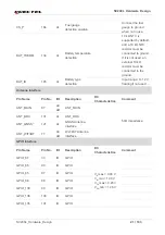
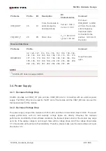
USB_BOOT
46
DI
Force the module to
enter emergency
download mode
V
IL
max = 0.48 V
V
IH
min = 1.39 V
Pull down
USB_BOOT to GND
will force the module
enter emergency
download mode.
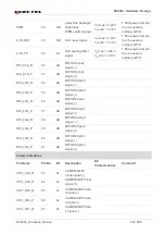
VIB_DRV_P 28 PO
Motor
drive
V
O
= 1.80~3.30 V
I
O
max = 100 mA
Connected to the
positive terminal of
the motor.
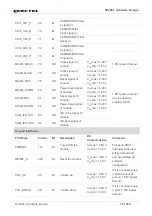
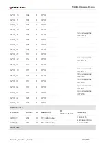
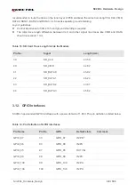
Reserved Interfaces
Pin Name
Pin No.
Comment
RESERVED
32
、
126
、
127
、
153
、
154
,
155
、
157
、
158
、
159
、
160
、
161
、
163
、
164
、
165
、
166
、
169
、
170
、
173
、
174
、
175
、
177
、
178
、
179
、
180
、
181
、
182
、
186
、
192
、
193
、
194
、
195
、
196
、
197
、
198
、
199
、
200
、
201
、
205
、
232
、
239
、
242
、
246
、
254
、
257
、
263
、
264
、
265
、
267
、
270
Keep these pins
open.


