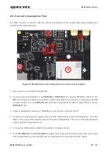
5G Module Series
5G-M2_EVB_User_Guide 24 / 34
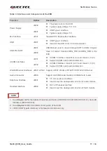
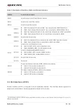
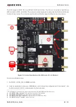
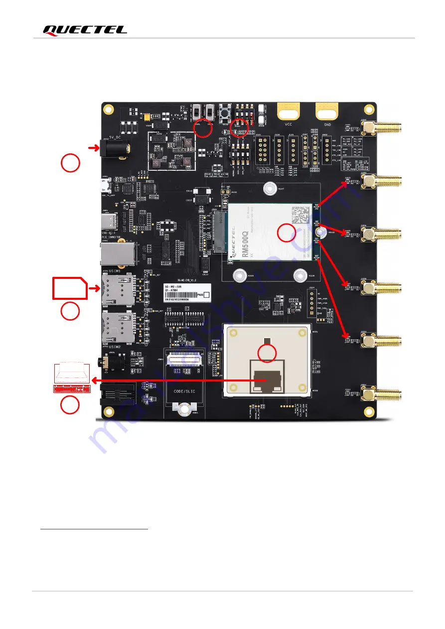
The EVB supports AF50T TE-A and RTL8111H/RTL8125 TE-A. The TE-A is connected to the EVB via
BTB connectors J0501 and J0502. The connectors allow engineers to easily test the WLAN and Ethernet
function of the module. The connection and function verification steps for Ethernet are shown below:
Micro-SIM
+5 V Power In
PC
Ethernet Cable
S0301.4=PCIE_SEL=H
2
2
3
3
4
4
5
5
1
1
6
6
7
7
RTL8111H/RTL8125 TE-A
RM500Q-GL 5G M.2 Module
Figure 18: Connections Between the EVB and a PC via Ethernet
Functional verification steps:
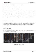
1. Set S0301.4 (PCIE_SEL) to
HIGH
level side.
2. Insert an applicable module (e.g., RM500Q-GL), which should be configured by AT Commands
2
, into
the M.2 connector (J0101), and assemble the four antennas.
2
The following AT commands are used to set the module into WLAN/Ethernet function mode:
⚫
AT+QCFG="data_interface",1,0
: switch the module to PCIe interface.
⚫
AT+QCFG="pcie/mode",1
: set the module to PCIe RC mode.
⚫
AT+QETH="eth_driver","R8168",1
: load the driver for RTL8111H TE-A.
⚫
AT+QETH="eth_at","enable"
: enable the driver.


