background image


BG95&BG96 

Compatible Design


LPWA Module Series 


Rev. BG95&BG96_Compatible_Design_V1.0 


Date: 2019-12-13 

      Status: Released 

www.quectel.com


Summary of Contents for BG95 Series

Page 1: ...BG95 BG96 Compatible Design LPWA Module Series Rev BG95 BG96_Compatible_Design_V1 0 Date 2019 12 13 Status Released www quectel com...

Page 2: ...ERS THE INFORMATION PROVIDED IS BASED UPON CUSTOMERS REQUIREMENTS QUECTEL MAKES EVERY EFFORT TO ENSURE THE QUALITY OF THE INFORMATION IT MAKES AVAILABLE QUECTEL DOES NOT MAKE ANY WARRANTY AS TO THE IN...

Page 3: ...LPWA Module Series BG95 BG96 Compatible Design BG95 BG96_Compatible_Design 2 47 About the Document Revision History Revision Date Author Description 1 0 2019 12 13 Ward WANG Mickey ZHANG Initial...

Page 4: ...off 26 4 3 1 Turn off Module via AT Command BG95 BG96 26 4 3 2 Turn off Module by PWRKEY and VBAT BG95 BG96 26 4 4 Reset 27 4 5 Network Status Indication 29 4 6 Operation Status Indication 29 4 7 U S...

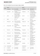
Page 5: ...BLE 2 FREQUENCY BANDS AND GNSS TYPES OF BG95 AND BG96 MODULES 8 TABLE 3 FEATURES OVERVIEW 10 TABLE 4 I O PARAMETERS DEFINITION 14 TABLE 5 PIN DEFINITION COMPARISON BETWEEN BG96 AND BG95 15 TABLE 6 POW...

Page 6: ...US 29 FIGURE 13 REFERENCE CIRCUIT OF U SIM INTERFACE WITH A 6 PIN U SIM CARD CONNECTOR 30 FIGURE 14 REFERENCE DESIGN OF U SIM CARD INTERFACE WITH U SIM CARD DETECTION 30 FIGURE 15 REFERENCE CIRCUIT WI...

Page 7: ...gn BG95 BG96_Compatible_Design 6 47 1 Introduction Quectel LTE Cat M1 Cat NB2 EGPRS module BG95 is compatible with Quectel LTE Cat M1 Cat NB1 EGPRS module BG96 This document briefly describes the comp...

Page 8: ...onnectivity on LTE FDD GPRS EGPRS networks and supports half duplex operation in LTE networks It also provides GNSS and voice 2 functionality to meet customers specific application demands BG95 includ...

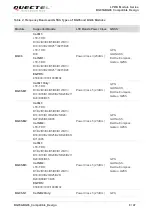
Page 9: ...E FDD B1 B2 B3 B4 B5 B8 B12 B13 B14 B18 B19 B20 B25 B26 B27 B28 B66 B85 Power Class 5 21dBm GPS GLONASS BeiDou Compass Galileo QZSS BG95 M2 Cat M1 LTE FDD B1 B2 B3 B4 B5 B8 B12 B13 B14 B18 B19 B20 B25...

Page 10: ...B5 B8 B12 B13 B18 B19 B20 B25 B26 B28 B31 B66 B72 B73 B85 Power Class 5 21dBm GPS GLONASS BeiDou Compass Galileo QZSS BG95 M5 Cat M1 LTE FDD B1 B2 B3 B4 B5 B8 B12 B13 B14 B18 B19 B20 B25 B26 B27 B28 B...

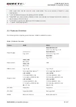
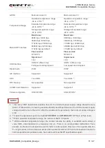
Page 11: ...mpares general features of BG95 and BG96 modules Table 3 Features Overview Feature BG96 BG95 Power Supply 3 3V to 4 3V Typ 3 8V BG95 M1 M2 N1 2 6V 1 to 4 8V Typ 3 3V BG95 M3 M5 3 3V 4 3V Typ 3 8V BG95...

Page 12: ...specified tolerances When the temperature returns to normal operation temperature levels the module will meet 3GPP specifications again GPRS Multi slot class 33 Multi slot class 33 Temperature Range...

Page 13: ...e_Design 12 47 5 5 BG95 supports ADC0 and ADC1 The two interfaces are internally connected therefore they cannot be used simultaneously If the two ADC interfaces are intended to be used at the same ti...

Page 14: ...RKEY 1 DBG_RXD DBG_TXD ADC0 VDD_EXT DTR GND USIM_CLK USIM_DATA USIM_RST USIM_VDD RI DCD RTS TXD RXD VBAT_BB USIM_GND GND CTS I2C_SCL I2C_SDA USIM_PRESENCE VBAT_BB GND GND GND RESERVED VBAT_RF VBAT_RF...

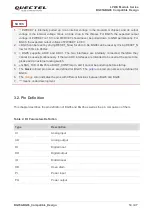
Page 15: ...aces are internally connected therefore they cannot be used simultaneously If the two ADC interfaces are intended to be used at the same time please add an external analog switch 4 4 GNSS_TXD of BG95...

Page 16: ...M clock output 1 8V power domain 5 PCM_SYNC DO PCM frame synchronization output 1 8V power domain PCM_SYNC DO PCM frame synchronization output 1 8V power domain 6 PCM_IN IO PCM data input 1 8V power d...

Page 17: ...1 NETLIGHT DO Indicate the module s network activity status 1 8V power domain NET_STATUS DO Indicate the module s network activity status 1 8V power domain 22 DBG_RXD DI Receive data 1 8V power domain...

Page 18: ...r supply for module s baseband part BG95 M1 M2 N1 2 6V 5 4 8V Typ 3 3V BG95 M3 M5 3 3V 4 3V Typ 3 8V BG95 M4 Typ 3 8V 34 RXD DI Receive data 1 8V power domain MAIN_RXD DI Receive data 1 8V power domai...

Page 19: ...ignal of U SIM card 1 8V 3 0V U SIM card supported USIM_RST DO Reset signal of U SIM card Only 1 8V U SIM card supported 45 USIM_DATA IO Data signal of U SIM card 1 8V 3 0V U SIM card supported USIM_D...

Page 20: ...62 GND Ground GND Ground 63 RESERVED RESERVED 64 GPIO64 IO General purpose input output interface 1 8V power domain GPIO3 IO General purpose input output interface 1 8V power domain 65 RESERVED GPIO4...

Page 21: ...es are intended to be used at the same time please add an external analog switch 3 3 PWRKEY is internally pulled up to an internal voltage in the Qualcomm chipset and its output interface 1 8V power d...

Page 22: ...G96 can be reset by driving RESET_N low for 150ms to 460ms 5 5 For every VBAT transition re insertion from 0V the minimum power supply voltage should be more than 2 7V Meanwhile in order to guaranteed...

Page 23: ...network If the voltage drop between the input and output is not too high it is recommended to use an LDO to supply power for the module If there is a big voltage difference between the input source a...

Page 24: ...ge Drop The power supply range of BG95 and BG96 modules are listed below BG96 and BG95 M3 M5 3 3V to 4 3V typ 3 8V BG95 M1 M2 N1 2 6V to 4 8V typ 3 3V BG95 M4 typ 3 8V Please make sure the input volta...

Page 25: ...is internally pulled up to an internal voltage in the Qualcomm chipset and its output voltage is the internal voltage minus a diode drop in the chipset For BG95 the expected output voltage of PWRKEY...

Page 26: ...igure 5 Power on Scenario BG95 BG96 Table 6 Power on Timing of BG95 BG96 Module T1 T2 T3 T4 T5 VILmax BG96 30ms 500ms 4 8s 4 2s 4 9s 0 5V BG95 30ms 500ms 1s 2 1s Typ 2 55s Typ 2 5s Typ 0 45V 1 For BG9...

Page 27: ...tely disconnecting the power supply The power off scenario of BG95 BG96 is illustrated in the figure below STATUS VBAT AT QPOWD T1 RUNNING Power down procedure OFF BG95 BG96 RXD BG95 BG96 Figure 6 Pow...

Page 28: ...1 T2 BG96 0 5V 650ms 2s BG95 0 45V 650ms 1 5s 1 3s 4 4 Reset BG95 can be reset by driving RESET_N low for 2s to 3 8s BG96 can be reset by driving RESET_N low for 150ms to 460ms The recommended circuit...

Page 29: ...s illustrated in the figure below VBAT T1 Resetting Module Status Running RESET_N Restart T2 VILmax Figure 10 Reset Scenario BG95 BG96 Table 7 Reset Timing of BG95 BG96 Module VILmax T1 T2 BG96 0 5V 1...

Page 30: ...reference circuit is shown in the following figure 4 7K 47K VBAT 2 2K Module BG96 NETLIGHT BG95 NET_STATUS Figure 11 Reference Circuit of NETLIGHT 4 6 Operation Status Indication BG95 BG96 provides a...

Page 31: ...GND GND 15K USIM_VDD USIM_GND BG95 BG96 USIM_VDD USIM_RST USIM_CLK USIM_DATA Figure 13 Reference Circuit of U SIM Interface with a 6 Pin U SIM Card Connector If U SIM card detection function needs to...

Page 32: ...s recommended to reserve series resistors for the U SIM signals of the module The 33 pF capacitors are used for filtering interference of EGSM900 Please note that the U SIM peripheral circuit should b...

Page 33: ...cuit with Translator Chip Another example with transistor translation circuit is shown as below For the design of circuits in dotted lines please refer to that of circuits in solid lines but please pa...

Page 34: ...odes The following figure shows a reference design of USB interface when application processor communicates with BG96 via USB interface USB_DP USB_DM GND USB_DP USB_DM GND L1 Close to Module R3 R4 Tes...

Page 35: ...wer sensitive applications it is recommended that USB is used for firmware upgrade only 4 10 PCM and I2C Interfaces BG95 BG96 provides one PCM digital interface and one I2C interface A reference desig...

Page 36: ...nterfaces of BG95 BG96 please refer to document 1 and 2 1 ADC input voltage must not exceed 1 8V 2 It is prohibited to supply any voltage to ADC pins when VBAT is removed 3 It is recommended to use re...

Page 37: ...IN and ANT_GNSS The RF antenna ports has an impedance of 50 In order to achieve better RF performance a type matching circuit is recommended to be reserved and type matching components R1 C1 C2 should...

Page 38: ...ntenna VDD Module ANT_GNSS 47nH 10R 0 1uF 0R NM NM 100pF Figure 21 Reference Circuit of ANT_GNSS Interface BG95 BG96 1 An external LDO can be selected to supply power according to the active antenna r...

Page 39: ...nd stencil design for BG95 and BG96 modules All dimensions are measured in millimeter mm and the dimensional tolerances are 0 05mm unless otherwise specified 5 1 Recommended Compatible Footprint The f...

Page 40: ...esign 39 47 Figure 23 Recommended Footprint of BG95 BG96 Top View 5 2 Recommended Stencil Design In order to ensure the module soldering quality the thickness of stencil is recommended to be 0 13mm to...

Page 41: ...es BG95 BG96 Compatible Design BG95 BG96_Compatible_Design 40 47 5 3 Installation Sketch Map The following figure shows the sketch map of installation for BG95 and BG96 Figure 24 Installation Sketch M...

Page 42: ...pass It is suggested that the peak reflow temperature is 238 C 245 C and the absolute maximum reflow temperature is 245 C To avoid damage to the module caused by repeated heating it is strongly recom...

Page 43: ...e ready to be soldered onto the application The following figures show the packaging details measured in millimeter mm BG96 The reel is 330mm in diameter and each reel contains 250 modules Factor Reco...

Page 44: ...WA Module Series BG95 BG96 Compatible Design BG95 BG96_Compatible_Design 43 47 Figure 26 Tape Dimensions of BG96 Direction of feed Cover tape 13 100 44 5 0 20 0 00 48 5 Figure 27 Reel Dimensions of BG...

Page 45: ...LPWA Module Series BG95 BG96 Compatible Design BG95 BG96_Compatible_Design 44 47 BG95 The reel is 330mm in diameter and each reel contains 250 modules Figure 28 Tape Dimensions of BG95...

Page 46: ...ns of BG95 Table 9 Packaging Specifications of BG95 BG96 Model Name MOQ for MP Minimum Package 250pcs Minimum Package 4 1000pcs BG96 250pcs Size 370mm 350mm 56mm N W 1 0kg G W 1 71kg Size 380mm 250mm...

Page 47: ...on DTR Data Terminal Ready EDGE Enhanced Data rates for GSM Evolution EGPRS Enhanced GPRS e I DRX Extended Idle Mode Discontinuous Reception ESD Electrostatic Discharge FDD Frequency Division Duplex S...

Page 48: ...ted Circuit LDO Low Dropout Regulator LED Light Emitting Diode LGA Land Grid Array LPWA Low Power Wide Area LTE Long Term Evolution PCB Printed Circuit Board PCM Pulse Code Modulation QZSS Quasi Zenit...

Reviews: