LPWA Module Series
BG95 Hardware Design
BG95_Hardware_Design 3 / 80
Contents
About the Document ................................................................................................................................ 2
Contents .................................................................................................................................................... 3
Table Index ............................................................................................................................................... 5
Figure Index .............................................................................................................................................. 7
1
Introduction ....................................................................................................................................... 8
1.1.
Safety Information .................................................................................................................... 9
2
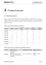
Product Concept ............................................................................................................................. 13
2.1.
General Description ................................................................................................................ 13
2.2.
Key Features .......................................................................................................................... 15
2.3.
Functional Diagram ................................................................................................................ 18
2.4.
Evaluation Board .................................................................................................................... 19
3
Application Interfaces ..................................................................................................................... 20
3.1.
Pin Assignment ...................................................................................................................... 21
3.2.
Pin Description ....................................................................................................................... 22
3.3.
Operating Modes .................................................................................................................... 29
3.4.
Power Saving ......................................................................................................................... 30
3.4.1.
Airplane Mode .............................................................................................................. 30
3.4.2.
Power Saving Mode (PSM).......................................................................................... 31
3.4.3.
Extended Idle Mode DRX (e-I-DRX) ............................................................................ 32
3.4.4.
Sleep Mode* ................................................................................................................ 32
3.4.4.1.
UART Application .............................................................................................. 32
3.5.
Power Supply ......................................................................................................................... 33
3.5.1.
Power Supply Pins ....................................................................................................... 33
3.5.2.
Decrease Voltage Drop ............................................................................................... 34
3.5.3.
Monitor the Power Supply ............................................................................................ 35
3.6.
Turn on and off Scenarios ...................................................................................................... 35
3.6.1.
Turn on Module Using the PWRKEY Pin ..................................................................... 35
3.6.2.
Turn off Module ............................................................................................................ 37
3.6.2.1.
Turn off Module Using the PWRKEY Pin ........................................................... 37
3.6.2.2.
Turn off Module Using AT Command ................................................................ 38
3.7.
Reset the Module ................................................................................................................... 38
3.8.
(U)SIM Interface ..................................................................................................................... 40
3.9.
USB Interface ......................................................................................................................... 42
3.10.
UART Interfaces ..................................................................................................................... 44
3.11.
PCM* and I2C* Interfaces ...................................................................................................... 47
3.12.
Network Status Indication ....................................................................................................... 48
3.13.
STATUS ................................................................................................................................. 49
3.14.
Behaviors of RI* ..................................................................................................................... 49
3.15.
USB_BOOT Interface ............................................................................................................. 50
3.16.
ADC Interfaces ....................................................................................................................... 51


