LTE-A Module Series
EG12 Hardware Design
EG12_Hardware_Design 28 / 97
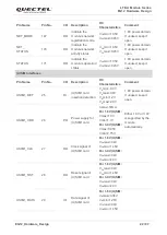
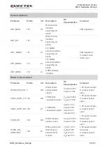
Antenna Interfaces
Pin Name
Pin No.
I/O
Description
DC
Characteristics
Comment
ANT_MAIN
107
IO
Main antenna
interface
supporting all
bands
50Ω impedance
ANT_DIV
127
AI
RXD antenna
interface
supporting all
bands
50Ω impedance
If unused, keep
them open.
ANT_ MIMO1
101
AI
4×4 MIMO
antenna interface
supporting all
bands
ANT_MIMO2
113
AI
4×4 MIMO
antenna interface
supporting all
bands
ANT_GNSS
119
AI
GNSS antenna
interface
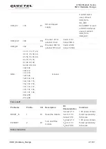
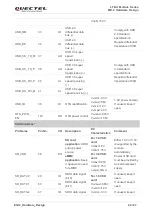
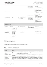
WLAN Control Interface*
Pin Name
Pin No.
I/O
Description
DC
Characteristics
Comment
WLAN_PWR_EN 5
DO
WLAN power
supply enable
control
V
OL
max=0.45V
V
OH
min=1.35V
1.8V power domain.
If unused, keep it
open.
COEX_UART_TX 145
DO
LTE/WLAN
coexistence signal
V
OL
max=0.45V
V
OH
min=1.35V
1.8V power domain.
If unused, keep it
open.
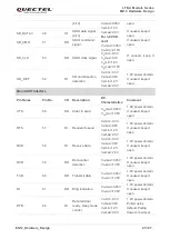
COEX_UART_RX 146
DI
LTE/WLAN
coexistence signal
V
IL
min=-0.3V
V
IL
max=0.6V
V
IH
min=1.2V
V
IH
max=2.0V
1.8V power domain.
If unused, keep it
open.
WLAN_EN
149
DO
WLAN function
enable control
V
OL
max=0.45V
V
OH
min=1.35V
1.8V power domain.
Active high.
If unused, keep it
open.
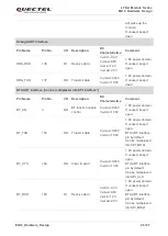
WAKE_ON_
WIRELESS
160
DI
Wake up the host
(EG12) by an
external Wi-Fi
module
V
IL
min=-0.3V
V
IL
max=0.6V
V
IH
min=1.2V
V
IH
max=2.0V
1.8V power domain.
Active low.
If unused, keep it
open.

