LTE-A Module Series
EG12 Hardware Design
EG12_Hardware_Design 29 / 97
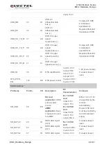
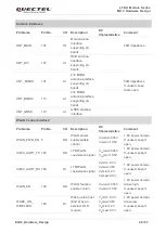
WLAN_SLP_
CLK
169
DO
WLAN sleep clock
V
OL
max=0.45V
V
OH
min=1.35V
If unused, keep it
open.
ADC Interfaces
Pin Name
Pin No.
I/O
Description
DC
Characteristics
Comment
ADC0
173
AI
General purpose
analog to digital
converter interface
Voltage range:
0V to 1.875V
If unused, keep it
open.
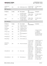
ADC1
175
AI
General purpose
analog to digital
converter interface
Voltage range:
0V to 1.875V
If unused, keep it
open.
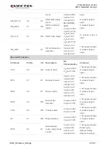
PCIe Interface*
Pin Name
Pin No.
I/O
Description
DC
Characteristics
Comment
PCIE_REF
CLK_P
179
AI/
AO
Input/Output PCIe
reference clock (+)
Comply with PCIe
2.1 standard
specifications.
Require differential
impedance of 95Ω.
PCIE_REF
CLK_M
180
AI/
AO
Input/Output PCIe
reference clock (-)
PCIE_TX_M
182
AO
PCIe transmission
(-)
PCIE_TX_P
183
AO
PCIe transmission
(+)
PCIE_RX_M
185
AI
PCIe receiving (-)
PCIE_RX_P
186
AI
PCIe receiving (+)
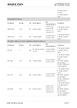
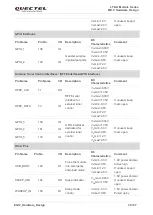
PCIE_CLK_
REQ_N
188
IO
PCIe clock request
V
OL
max=0.45V
V
OH
min=1.35V
V
IL
min=-0.3V
V
IL
max=0.6V
V
IH
min=1.2V
V
IH
max=2.0V
In master mode, it is
an input signal.
In slave mode, it is
an output signal.
If unused, keep it
open.
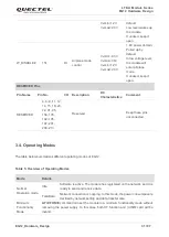
PCIE_RST_N
189
IO
PCIe reset
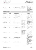
V
OL
max=0.45V
V
OH
min=1.35V
V
IL
min=-0.3V
V
IL
max=0.6V
V
IH
min=1.2V
V
IH
max=2.0V
In master mode, it is
an output signal.
In slave mode, it is
an input signal.
If unused, keep it
open.
PCIE_WAKE_N
190
IO
PCIe wake up
V
OL
max=0.45V
V
OH
min=1.35V
V
IL
min=-0.3V
V
IL
max=0.6V
In master mode, it is
an input signal.
In slave mode, it is
an output signal.

