LTE-A Module Series
EG12 Hardware Design
EG12_Hardware_Design 48 / 97
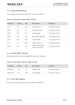
3.11.1. Main UART Interface
The following table shows the main UART interface pin definition.
Table 12: Pin Definition of Main UART Interface
3.11.2. Debug UART Interface
The following table shows the Debug UART interface pin definition.
Table 13: Pin Definition of Debug UART Interface
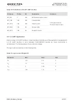
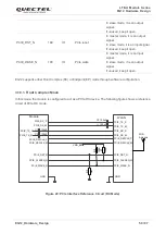
3.11.3. BT UART Interface
The following table shows the BT UART interface pin definition.
Pin Name
Pin No.
I/O
Description
Comment
CTS
56
DO
Clear to send
1.8V power domain
RTS
57
DI
Request to send
1.8V power domain
RXD
58
DI
Receive data
1.8V power domain
DCD
59
DO
Data carrier detection
1.8V power domain
TXD
60
DO
Transmit data
1.8V power domain
RI
61
DO
Ring indication
1.8V power domain
DTR
62
DI
Data terminal ready,
sleep mode control
1.8V power domain
Pin Name
Pin No.
I/O
Description
Comment
DBG_RXD
136
DI
Receive data
1.8V power domain
DBG_TXD
137
DO
Transmit data
1.8V power domain

