An external 10kΩ pull-down resistor is required.
Application external
0 = Pull-down, 1 = Pull-up.
Mode select bit 0
Mode select bit 1
Mode select bit 2
Mode select bit 3
weak pull-up/down
0
1
1
0
0
0
0
0
0
0
0
0
0
0
0
configuration signal
weak pull-up/down
EXT_INT_SEL
MODE 0
MODE 1
MODE 2
MODE 3
PHY_AD0
PHY_AD1
PHY_AD2
PHY core
1
Default internal
The upper two bits of the physical address are set to 00.
PHY_AD[2:0] set the lower three bits of the physical address.
Description
12
TITLE
PROJECT
Lorry XU
Woody WU
CHECKED BY
DRAWN BY
OF
A
6
5
4
3
2
1
SHEET
A
B
C
D
1
2
3
4
5
6
D
C
B
Quectel Wireless Solutions
SIZE
VER
14
1.0
DATE
2019/12/5
EG21-G
A2
Reference Design
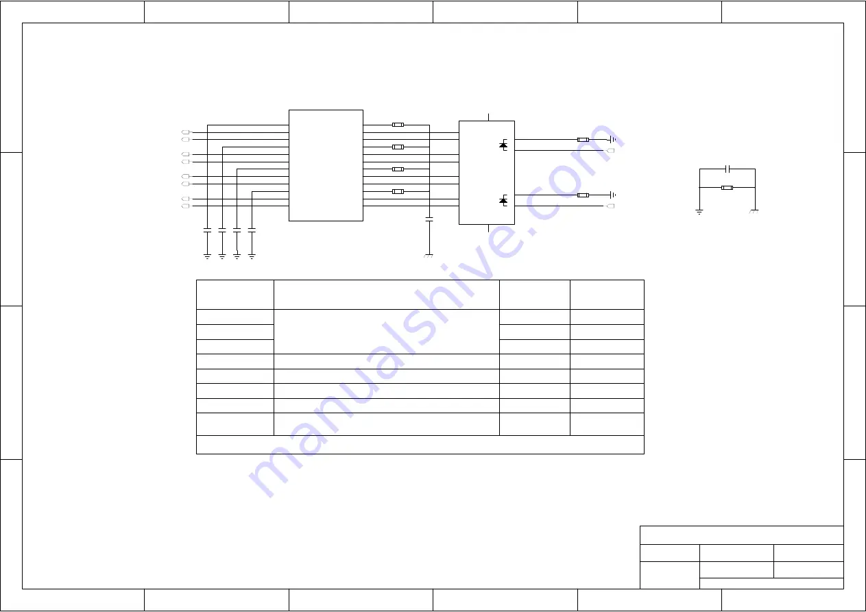
Ethernet Network Port Design
Notes:
1. Route MDI differential signals with 100Ω±10%, and the reference ground of the area should be complete.
2. Keep skew of the MDI differential signals less than 20mil, and the maximum trace length must be less than10 inches.
3. The connection method between MDI interface differential line and RJ45 line is 1/2, 3/6, 4/5 and 7/8.
4. To minimize crosstalk, the distance between separate adjacent pairs that are on the same layer must be equal to or larger than 40mil.
1 TCT1
2 TD1+
3 TD1-
4 TCT2
5 TD2+
6 TD2-
7 TCT3
8 TD3+
9 TD3-
10 TCT4
11 TD4+
12 TD4-
13
MX4-
14
MX4+
15
MCT4
16
MX3-
17
MX3+
18
MCT3
19
MX2-
20
MX2+
21
MCT2
22
MX1-
23
MX1+
24
MCT1
U1001
FC3004
C
1003
0.1uF
C
1004
0.1uF
C
1005
0.1uF
C
1006
0.1uF
1 TA+
14
H2
13
H1
3 TB+
5 TC-
7 TD+
2 TA-
4 TC+
6 TB-
8 TD-
9
G-
10
G+
11
Y-
12
Y+
J1001
FC601-56-LED
R1001
75R 1%
R1003
75R 1%
R1004
75R 1%
R1006
75R 1%
C1001
NM_1000pF/2KV
C1002
1000pF/2KV
R1002
510R
R1007
510R
R1005
0R
[11]
LED_ACT
[11]
LED_1000
[11] TRXP0
[11]TRXN0
[11]TRXP1
[11]TRXN1
[11]TRXP2
[11] TRXN2
[11] TRXP3
[11] TRXN3


