LTE Standard Module Series
EG25-GL_Hardware_Design 56 / 96
SGMII_MDIO
SGMII_INT_N
MDIO
RSTN
MDC
R1
R2
10K
VDD_EXT
Module
AR8033
1.5K
SGMII_MDIO_VDD
SGMII_RST_N
INT
SGMII_MDC
C1
C2
C3
C4
SGMII_TX_M
SGMII_TX_P
SGMII_RX_P
SGMII_RX_M
SIP
SIN
SOP
SON
Close to Module
Close to AR8033
Control
SGMII Data
0.1
μ
F
SGMII_MDIO_VDD
SGMII_MDIO_VDD
0.1
μ
F
0.1
μ
F
0.1
μ
F
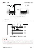
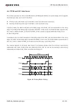
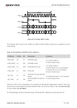
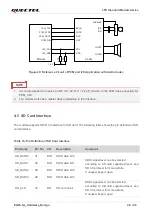
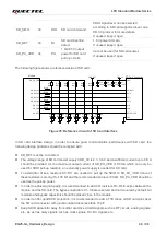
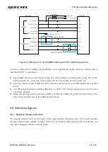
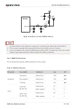
Figure 28: Reference Circuit of SGMII Interface with PHY AR8033 Application
In order to enhance the reliability and availability in your applications, please follow the criteria below in
the Ethernet PHY circuit design:
⚫
Keep SGMII data and control signals away from other sensitive circuits/signals such as RF circuits,
analog signals, etc., as well as noisy signals such as clock signals, DC-DC signals, etc.
⚫
Keep the maximum trace length less than 10 inches and keep skew on the differential pairs less than
20 mil.
⚫
The differential impedance of SGMII data trace is 100
Ω ±10%, and the reference ground of the area
should be complete.
⚫
Make sure the trace spacing between SGMII_TX_P/M and SGMII_RX_P/M is at least 3 times of the
trace width, and the same to the adjacent signal traces.
4.9 Indication Signals
4.9.1 Network Status Indication
The network indication pins can be used to drive network status indication LEDs. The module provides
two pins which are NET_MODE and NET_STATUS. The following tables describe the pin definition and
logic level changes in different network status.


