GV100 User manual
3.4.
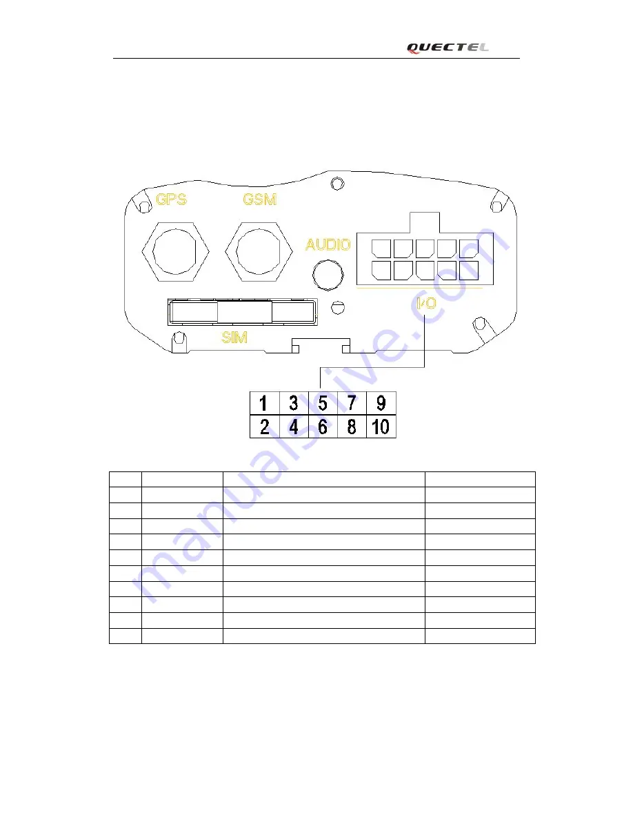
I/O Interface
There are several inputs and outputs on I/O cable and the definition are:
Index
Color on I/O cable
Description
Recommended Function
1
White
Input 2 (Digital , Positive Trigger)
2
Black
Input 3 (Digital , Positive Trigger, With interrupt)
3
Brown
Input 4 (Digital , Negative Trigger, With interrupt)
Panic Button
4
Yellow
Input 5 (Digital , Negative Trigger)
5
Gray
Input 6 (Analog, Input voltage range : 0 – 28 V)
6
Purple
Digital Output 2 (Negative Trigger)
7
Red
Digital Output 3 (Negative Trigger)
8
Green
Digital Output 4 (Negative Trigger)
9 Orange
10
Blue
Digital Output 5 (Built in Relay)
TRACGv100UM001
- 14 -


