L50 Hardware Design
L50_HD_V1.0 -16-
3.3 Operating Modes
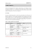
The table below briefly summarizes the various operating modes in the following chapters.
Table 6: Overview of operating modes
Mode
Function
Acquisition mode
The module starts to search satellites and determine visible satellites
,
coarse
carrier frequency and code phase of satellite signals. When the acquisition is
completed, it switches to tracking mode automatically.
Tracking mode
The module refines acquisition’s message, as well as keeping tracking and
demodulating the navigation data from the specific satellites.
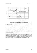
Hibernate mode
The module can be switched to hibernate mode by applying a pulse which
consists of a rising edge and high level that persists for at least 1ms on the
ON_OFF pin.
3.4 Power Management
There are two power supply pins in L50, VCC and VIO/RTC.
3.4.1 VCC Power
VCC pin supplies power for GPS BB domain and GPS RF domain. The power supply VCC’s current
varies according to the processor load and satellite acquisition. Typical VCC max current is 100 mA.
So it is important that the power is clean and stable. Generally, ensure that the VCC supply ripple
voltage meet the requirement: 54 mV(RMS) max @ f = 0~3MHz
and 15 mV(RMS) max @ f > 3
MHz.
Table 7: Pin definition of the VCC pin
3.4.2 VIO/RTC Power
The VIO/RTC pin supplies power for all RTC domain and CMOS I/O domain, so VIO/RTC should be
powered all the time when the module is running. It ranges from 1.71V to 1.89V. In order to achieve a
better Time To First Fix (TTFF) after VCC power down, VIO/RTC should be valid all the time. It can
supply power for SRAM memory which contains all the necessary GPS information for quick start-up
and a small amount of user configuration variables.
Name
Pin
Function
VCC
2
power supply for GPS BB and RF part
Quectel
Preliminary


