GNSS Module Series
L89_R2.0_EVB_User_Guide 13 / 25
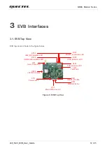
3.2.
EVB Interfaces
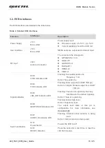
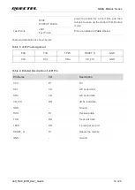
The EVB interfaces are detailed in the table below.
Table 2: Detailed EVB Interfaces
Function
Interfaces
Description
Power Supply
J103
Micro-USB
Power supply input:
⚫
DC power supply: 4.5
–5.5 V, typ. 5.0 V
⚫
Current capability should be >200 mA
User Interface
J103
Micro-USB
NMEA sentence output and command input.
RF Input
J403
Antenna Connector
The antenna in the kit supports:
⚫
GPS/QZSS L1 C/A
⚫
Galileo E1
⚫
GLONASS L1
⚫
BeiDou B1I
⚫
IRNSS L5
⚫
SBAS L1
Signal Indication
D303
1PPS Indication LED
Flashing: Successful position fix.
Frequency: 1 Hz.
Extinct: No position fix.
D304
TXD Indication LED
Flashing: Data output from UART TXD pin.
Extinct or Bright: No data output from UART
TXD pin.
D305
JAM_IND Indication LED
Flashing: There is some jamming that may
interfere with the desired signal(s).
Extinct: There is no jamming.
D306
GEOFENCE Indication LED
Flashing: Output high level.
Extinct: Output low level.
The output level state of this pin is
configurable. For more information, see
document [3]
D307
AADET_N Indication LED
Flashing: External active antenna is being
used.
Extinct: Internal antenna is being used.
Switch and Button
S101
Power Switch
Powers the EVB on/off.
S301
RESET_N Button
Press the button for a short time to reset the
L89 R2.0 module.


