M20 Hardware Design
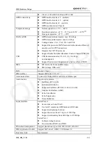
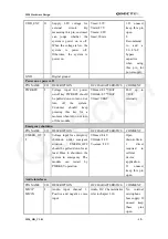
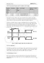
Table 7: Recommended bypass capacitors for limited current supply
Maximum
current
output of
power
supply
Capacitance
ESR@
+25
°C
100KHz
(
Ω
)
Part number
Quantity of
application
Vendor
1.5A 1500µF <=0.045
592D158X06R3R2T20H
1 VISHAY
1A 2200µF
<=0.055
592D228X06R3X2T20H
2 VISHAY
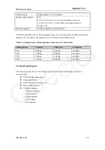
The single 3.6V Li-Ion cell battery type can be connected to the power supply of the module
VBAT directly. But the Ni_Cd or Ni_MH battery must be used carefully, since their maximum
voltage could rise over the absolute maximum voltage for the module and damage it.
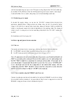
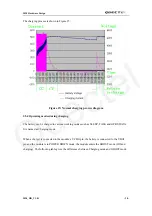
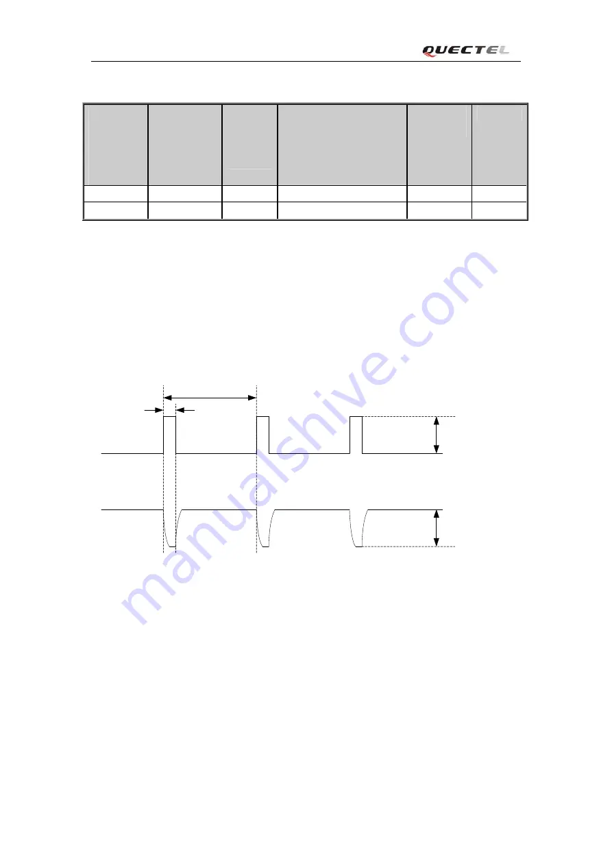
The RF Power Amplifier current (1.6A peak in GSM/GPRS mode) flows with a ratio of 1/8 of
time, around 577us every 4.615ms, in talking mode. Figure 4 shows the VBAT voltage drop and
current ripple at the maximum power transmitting phase, the test condition is VBAT=4.0V,
VBAT voltage source maximum output current =2A, C1=100µF tantalum capacitor (ESR=0.7
Ω
)
and C2=1µF.
Max:400mV
Burst:1.6A
4.615ms
577us
IBAT
VBAT
Figure 4
: Ripple in supply voltage during transmitting burst
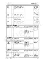
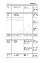
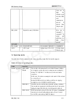
3.3.1 Power supply pins
The VBAT pins are dedicated to connect the supply voltage; and the GND pins are recommended
for grounding. VRTC pin can be used to connect a rechargeable coin battery or a golden capacitor
which can help to maintain the system clock when VBAT supply is not applied.
3.3.2 Minimizing power losses
Please pay special attention to the power supply design for your applications. Please make sure
that the input voltage will never drop below 3.4V even in a transmitting burst during which the
M20_HD_V1.01
- 25 -
Quectel

