M20 Hardware Design
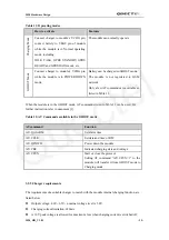
Table 11: Operating modes
How to activate
Features
C
ha
rg
in
g
M
od
e
Connect charger to module’s VCHG pin,
connect battery to VBAT pin of module
while the module is in Normal operating
mode, including:
IDLE, TALK, GPRS STANDBY, GPRS
READY and GPRS DATA mode, etc.
The module can normally operate.
GHOST
Mo
de
Connect charger to module’s VCHG pin
while the module is in POWER DOWN
mode.
Battery can be charged in GHOST mode.
The module is not registered to GSM
network.
Only a few AT commands are available as
listed in Table 12.
When the module is in the GHOST mode, AT commands listed in Table 12 can be used. For
further instruction refer to document [1].
Table 12: AT Commands available in the GHOST mode
AT command
Function
AT+QALARM
Set alarm time
AT+CCLK
Set data and time of RTC
AT+QPOWD
Power down the module
AT+CBC
Indicated charging state and voltage
AT+CFUN
Start or close the protocol
Setting AT command “AT+CFUN=1” to the
module will transfer it from GHOST mode to
Charging mode.
3.5.5 Charger requirements
The requirements of a suitable charger to match with the module internal charging function are
listed below:
z
Output voltage: 4.6V~6.5V
,
nominal voltage level is 5.0V.
z
Charging current limitation: 650mA
z
A 10V peak voltage is allowed for maximum 1ms when charging current is switched off.
M20_HD_V1.01
- 39 -
Quectel

