M20 Hardware Design
Synchronization between DTE and DCE
:
When DCE (the module) powers on with the autobauding enabled, it is recommended to wait for 2
to 3 seconds before sending the first AT character. After receiving the “OK” response, DTE and
DCE are correctly synchronized.
Restrictions on autobauding operation
z
The serial port has to be operated at 8 data bits, no parity and 1 stop bit (factory setting).
z
The Unsolicited Result Codes like "RDY", "+CFUN: 1" and "+CPIN: READY” are not
indicated when you start up the module while autobauding is enabled
,
because the baud rate
used by the host controller can not be detected before inputting AT character .
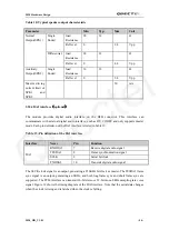
Serial Port 1
z
Two data lines: TXD1 and RXD1
z
Two hardware flow control lines: RTS1 and CTS1
z
Serial port 1 is used for software debugging. It cannot be used for AT command, GPRS
service, CSD call and FAX call. It doesn’t support multiplexing and autobauding function.
3.9.2 Software upgrade and software debug
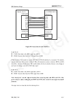
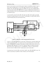
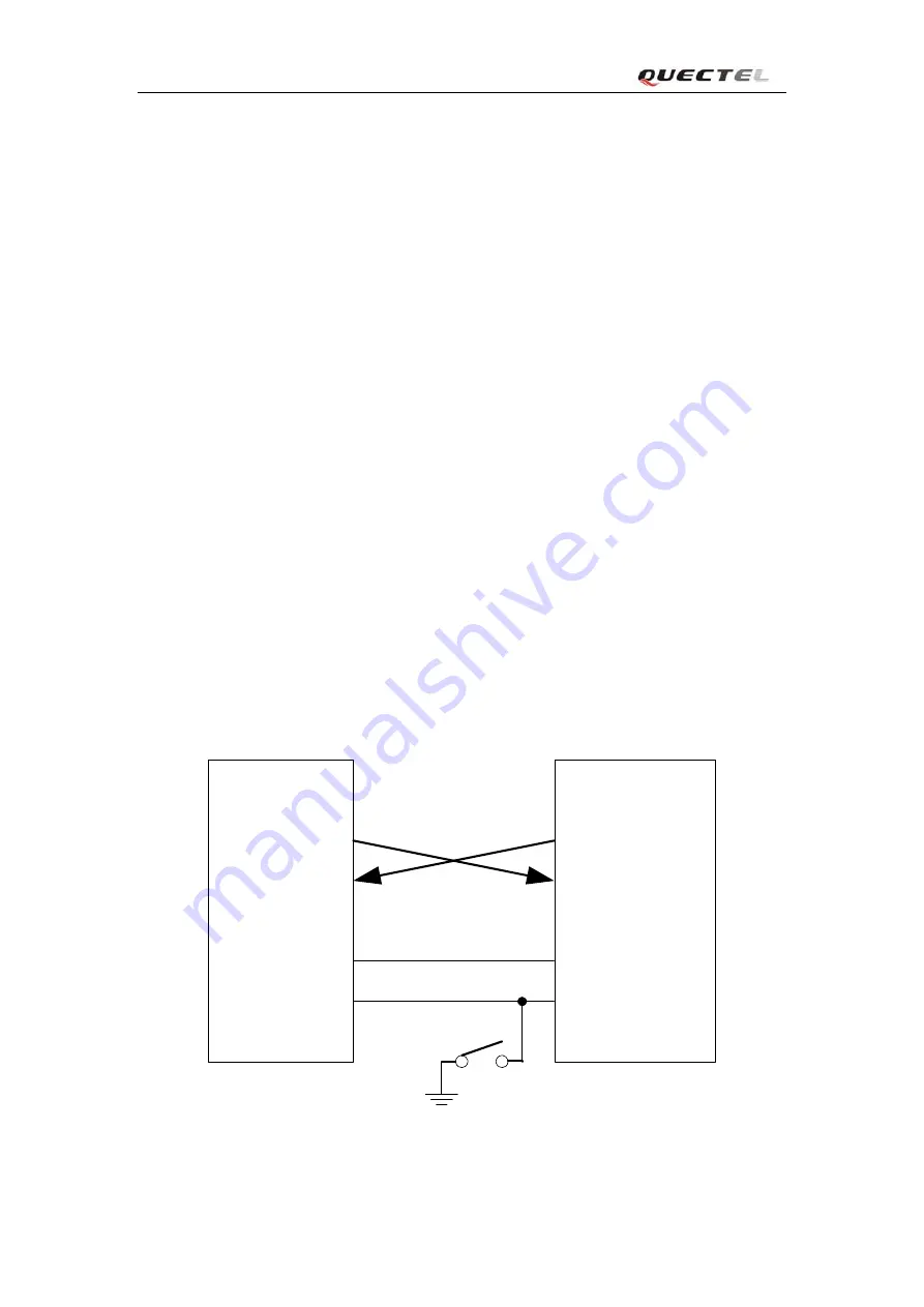
The TXD0
、
RXD0 can be used to upgrade software, while TXD1
、
RXD1 can be used for software
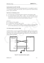
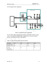
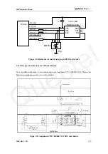
debugging. Customer can insert a switch between the PWRKEY and the GND. The PWRKEY pin
must be pulled down during the software upgrade process. Please refer to the following figures for
software upgrade and debugging.
IO CONNECTOR
TXD
RXD
GND
PWRKEY
Module (DCE)
Serial port0
TXD0
RXD0
GND
PWRKEY
Figure 21
: Connection of software upgrade
M20_HD_V1.01
- 46 -
Quectel

