Smart Wi-Fi Module Series
SC20-WL Hardware Design
SC20-WL_Hardware_Design
65 / 81
5
Antenna Interface
SC20-WL antenna interface includes a Wi-Fi/BT antenna. The antenna interface has an impedance of
50
Ω.
5.1. Wi-Fi/BT Antenna Interface
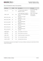
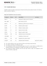
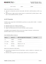
The following tables show the Wi-Fi/BT antenna pin
’s definition and frequency specification.
Table 27: Pin Definition of Wi-Fi/BT Antenna
Table 28: Wi-Fi/BT Frequency
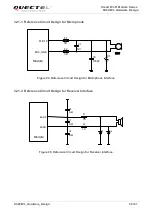
A reference circuit design for Wi-Fi/BT antenna is shown as below. R1, C1 and C2 are mounted according
to the actual debugging. C1 and C2 are not mounted and a 0
Ω resistor is mounted on R1 by default.
ANT_WIFI/BT
R1 0R
C1
Module
2.4Ghz/
5Ghz
antenna
NM
C2
NM
Figure 29: Reference Circuit Design for Wi-Fi/BT Anternna
Pin Name
Pin No.
I/O
Description
Comment
ANT_WIFI/BT
77
IO
Wi-Fi/BT antenna
50
Ω impedance
Type
Frequency
Unit
802.11a/b/g/n/ac
2402~2482
5180~5825
MHz
BT4.2 LE
2402~2480
MHz


