Smart Wi-Fi Module Series
SC20-WL Hardware Design
SC20-WL_Hardware_Design
45 / 81
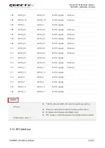
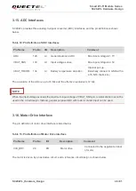
SC20-WL provides one SPI interface multiplexed from GPIO interfaces. The interface only supports the
master mode.
Table 12: Pin Definition of SPI Interface
3.14. I2C Interfaces
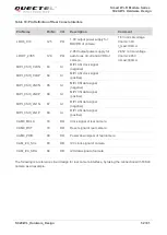
SC20-WL provides 3 groups of I2C interfaces which only support the master mode. As an open drain
output, the I2C interfaces need a pull-up resistor on its external circuit, and the recommended logic level
is 1.8V.
Table 13: Pin Definition of I2C Interface
Pin Name
Pin No
I/O
Comment
Description
GPIO_8
119
IO
GPIO by default.
Can be multiplexed into SPI_MOSI.
Master out slave in of SPI
GPIO_9
118
IO
GPIO by default.
Can be multiplexed into SPI_MISO.
Master in slave out of SPI
GPIO_10
117
DO
GPIO by default.
Can be multiplexed into SPI_CS_N.
SPI chip select
GPIO_11
116
DO
GPIO by default.
Can be multiplexed into SPI_CLK.
SPI clock
Pin Name
Pin No
I/O Description
Comment
TP_I2C_SCL
47
OD
I2C clock signal of touch panel
Used for touch panel
TP_I2C_SDA
48
OD
I2C data signal of touch panel
CAM_I2C_SCL
83
OD
I2C clock signal of camera
Used for camera
CAM_I2C_SDA
84
OD
I2C data signal of camera
SENSOR_I2C_SCL
91
OD
I2C clock signal for external sensor
Used for external
sensor
SENSOR_I2C_SDA
92
OD
I2C data signal for external sensor


