Smart LTE Module Series
SC66 Hardware Design
SC66_Hardware_Design 50 / 139
Constant current mode (CC mode):
When the battery voltage is increased to between the
maximum pre-charge voltage and 4.35V (3.6V~4.5V programmable, 4.35V by default), the system
will switch to CC mode. The charging current is programmable from 0mA~3000mA. The default
charging current is 500mA for USB charging and 2A for adapter.
Constant voltage mode (CV mode):
When the battery voltage reaches the final value 4.35V, the
system will switch to CV mode and the charging current will decrease gradually. When the charging
current reduces to about 100mA, the charging is completed.
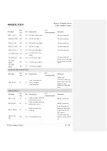
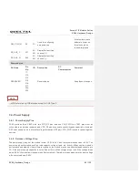
Table 11: Pin Definition of Charging Interface
Pin Name
Pin No.
I/O Description
Comment
USB_VBUS
41, 42
PI/PO
Charging power input.
Power supply output for OTG device.
USB/charger insertion detection.
Vmax=10V
Vmin=3.6V
Vnorm=5.0V
VBAT
36, 37,
38
PI/PO
Power supply for the module
Vmax=4.4V
Vmin=3.55V
Vnorm=4.0V
BAT_PLUS
27
AI
Differential input signal of battery voltage
detection (+)
Must be connected
BAT_MINUS
28
AI
Differential input signal of battery voltage
detection (-)
Must be connected
BAT_THERM
29
AI
Battery temperature detection
Internally pulled up.
Externally connected
to GND via a 47KΩ
NTC resistor.
SC66 module supports battery temperature detection in the condition that the battery integrates a
thermistor (47K 1% NTC thermistor with B-constant of 4050K by default; SDNT1608X473F4050FTF of
SUNLORD is recommended) and the thermistor is connected to VBAT_THERM pin. If VBAT_THERM pin
is not connected, there will be malfunctions such as boot error, battery charging failure, battery level
display error, etc.
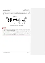
A reference design for battery charging circuit is shown below.

