Smart LTE Module Series
SC66 Hardware Design
SC66_Hardware_Design 44 / 139
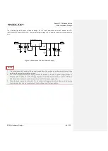
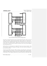
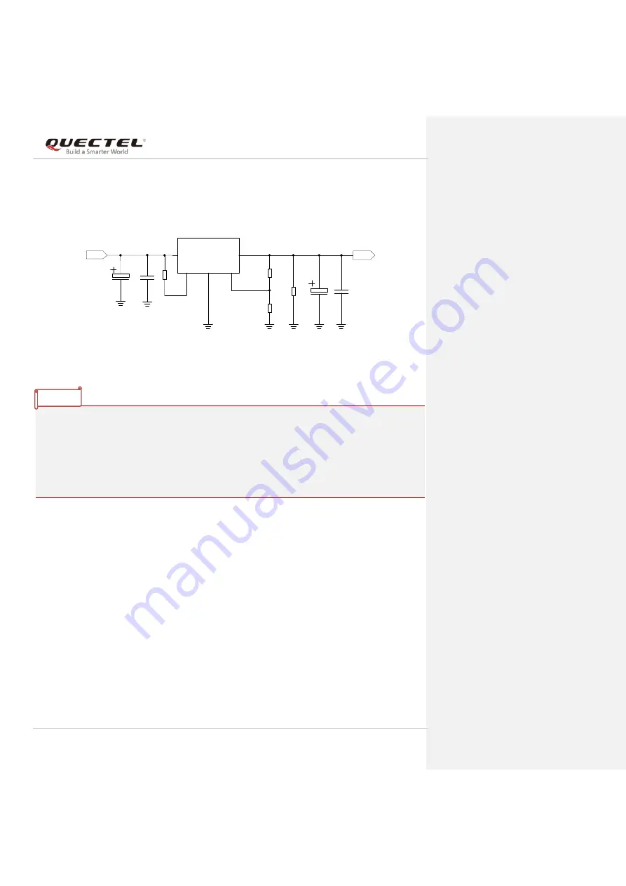
The following figure shows a reference design for +5V input power source which adopts an LDO
(MIC29502WU) from MICROCHIP. The typical output voltage is 4.0V and the maximum rated current is
5.0A.
DC_IN
C1
C2
MIC29502WU
U1
IN
OUT
EN
GND
ADJ
2
4
1
3
5
VBAT
100nF
C3
470uF
C4
100nF
R2
220K
100k
R3
470uF
470R
51K
R4
R1
1%
1%
Figure 5: Referfence Circuit of Power Supply
1. It is recommended to switch off the power supply when the module is in abnormal state, and then
switch on the power to restart the module.
2. The module supports battery charging function by default. If the above power supply design is
adopted, please make sure the charging function is disabled by software, or connect VBAT to
Schottky diode in series to avoid the reverse current to the power supply chip.
3. When the battery power is reduced to 0%, the system will trigger automatic shutdown, so the design
of power supply should be consistent with the configuration of fuel gauge driver.
NOTES

