LTE-A Module Series
UMTS<E EVB R2.0 User Guide
UMTS<E_EVB_R2.0_User_Guide 28 / 44
Table 8: Pin Definition of J701
4.7. UART Connectors (J401/J402)
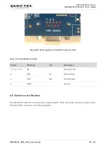
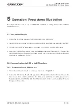
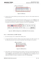
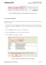
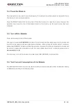
The UMTS<E EVB R2.0 offers two UART ports (COM1 and COM2) via two UART connectors J401
and J402.
The main UART port COM1 is intended for the communication between the module and the host
application. It can be used for data transmission and AT command communication.
The debug UART port COM2 supports 115200bps baud rate by default. It can be used for Linux console
and log output.
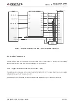
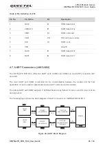
The following figure shows the block diagram of UART connectors on UMTS<E EVB R2.0.
J101
Module
RS-232
Level Match
3.0V/1.8V
Level Translator
COM1
DB9
J401
RS-232
3.0V
1.8V
U403
U401
RS-232
Level Match
3.0V/1.8V
Transistor Level
Translator
COM2
DB9
J402
RS-232
3.0V
U402
1.8V
U404
Figure 24: UART Block Diagram
Pin No.
Pin Name
I/O
Description
1
DAT2
IO
SDIO data (bit 2)
2
CD/DAT3
IO
SDIO data (bit 3)
3
CMD
DI
SDIO command
4
VDD
PO
SD card power supply
5
CLK
DI
SDIO clock
6
VSS
Ground
7
DAT0
IO
SDIO data (bit 0)
8
DAT1
IO
SDIO data (bit 1)

