background image

quest

quest

1-800-533-7533 

Quest 

DRY 

70 

Installation, Operation and Maintenance Instructions


6

www.QuestProtect.com

sales@QuestProtect.com

Quest 

DRY 

70 

Installation, Operation and Maintenance Instructions


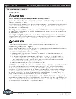
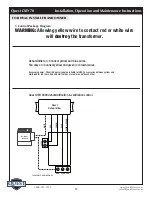
The installer must supply the wiring between the Quest Dry 70 and the control panel. Be sure to safely route 
the control wiring to prevent damage during installation. 

CAUTION 

Do not cross wires when connecting the Quest Dry 70 and the remote control panel or damage to the 
transformer may result. The remote controls of the Quest Dry 70 are powered by a low voltage circuit 
(24VAC) and must NEVER contact or be connected to a high voltage circuit. 

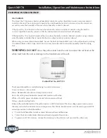
The control wires leaving the Quest Dry 70 and the remote control panels are numbered and color-coded to 
prevent confusion. Some of the control wires leaving the Quest Dry 70 may not be used with certain control 
panels and should be left unconnected with wire nuts taped onto the stripped ends for safety. Be sure to 
consult the electrical schematic in this manual or inside the access panel of the Quest Dry 70 before making 
control connections. 

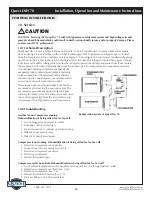
4.3 Condensate (Water) Removal 

CAUTION

A trap in the drain line is preferred, but not required for the unit to drain properly. Local codes may require 
a trap. Use care to keep the pipe assembly as flat to the floor as possible. Kinks and/or humps will prevent 
proper drainage. 

The Quest Dry 70 generates condensate. Install a 3/4" male nominal pipe thread adapter to the drain pan. 
It is necessary to assemble your own drain pipe assembly utilizing 3/4" PVC pipe to get the condensate to a 
floor or other drain. Pipe is commonly available in 10’ lengths from building supply, plumbing or hardware 
stores. Slope to drain should be at least 1” drop for every 10’ of run.  

4.3A Lifting Condensate 

A condensate pump may installed if lift is required to dispose of the condensate.  

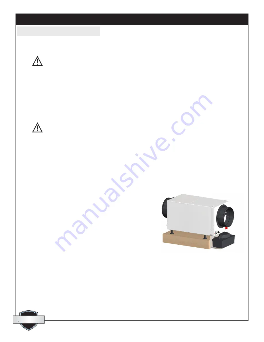
4.3B Condensate Pump Kit (4030113)

A condensate pump kit is available from the factory for use 
with the Quest Dry 70 and provides 15' of lift. Condensate is 
automatically pumped to a remote location when the water level 
in the pump’s reservoir rises to close the float switch. The pump 
also contains a safety float switch. The white leads from this switch 
extend from beneath the pump cover. This switch should be 
installed in series with the field wire that connects the blue (#5) 
lead from the Quest Dry 70 to the the control panel. If the pump 
fails, this switch opens the compressor control circuit and stops 
water production before the reservoir overflows. The Quest Dry 70 
will continue to ventilate or circulate air as normal, but will not 
dehumidify until this switch closes. 

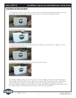
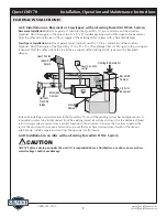
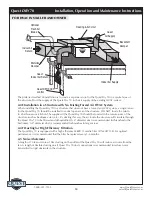
4.4 Converting to Vertical Discharge Airflow 

The QuestDry 70 is shipped from the factory with the exhaust 
panel of the cabinet configured for horizontal air discharge. The cabinet can be easily converted to vertical 
air discharge. To convert the air discharge from horizontal to vertical, follow these steps:

Condensate Pump Kit (4030113) shown installed. Available 

from your dealer or call 1-800-533-7533.

FOR HVAC INSTALLER ONLY

Summary of Contents for 4033750

Page 1: ...ssed thorough internal and 3rd party inspections for quality of workmanship and function Quest DRY150 Installation Operation and Maintenance Instructions 4201 Lien Rd Madison WI 53704 1 800 533 7533 w...

Page 2: ...ate Pump Kit 6 4 4 Ducting 6 4 4A Fresh Air Supply Air 7 4 4B Ducting for Fresh Air Option 7 4 4C Installation in a Basement or Crawlspace 8 4 4D Installation in an Attic 8 4 4E Installation in a Stru...

Page 3: ...ault Circuit Interrupt outlet DO NOT use the device as a bench or table DO NOT place the device directly on structural members A drain pan MUST be placed under the unit if installed above a living are...

Page 4: ...nce at 80 F and 60 RH Water Removal 65 pints day Efficiency 4 5 Pints kWh Air Filter MERV 11 Efficiency Standard 70 Efficient ASHRAE Dust Spot Test Size 12 x 12 x 1 Power Cord 8 110 120 VAC Grounded D...

Page 5: ...nded with a hang kit 4028111 or a suitable alternative from structural members as long as the suspending assembly supports the Quest Dry 70 s base in its entirety Do not hang the Quest Dry 70 from the...

Page 6: ...minal pipe thread adapter to the drain pan It is necessary to assemble your own drain pipe assembly utilizing 3 4 PVC pipe to get the condensate to a floor or other drain Pipe is commonly available in...

Page 7: ...ocated on the top of the unit Align screw holes and snap the panel onto the base 4 Secure the exhaust panel to the base by replacing the six 6 screws For the ideal installation draw air from the centr...

Page 8: ...red before entering the building 2 Outside air will be dehumidified before entering the building if the Quest Dry 70 is running in dehumidification mode 3 Drawing air from outside and blowing inside a...

Page 9: ...area of the structure Optional Duct the supply of the Quest Dry 70 to a 8 x 8 x 8 tee damper that is 20 open to the crawlspace if desired Duct the other side of the tee to the air supply of the exist...

Page 10: ...ooms den etc By ducting this way the air inside the structure will circulate through the Quest Dry 70 to be filtered and dehumidified A 6 diameter duct is recommended for branches to the bedrooms A 8...

Page 11: ...be sure the built in dehumidistat is set to the off position by turning it counterclokwise until it stops Failure to do so may cause the unit to sense the humidity from the wrong area WARNING DO NOT...

Page 12: ...G Allowing yellow wire to contact red or white wire will destroy the transformer Dehumidifier on Connect yellow and blue wires Fan only on Connect yellow and green or brown wires Accessory power 24vol...

Page 13: ...ge to the unit and invalidate the product warranty 6 2 Optional Fresh Air Intake Check and clean the screen on the outdoor fresh air intake port seasonally The screen may become plugged during the sea...

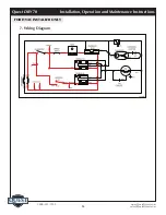
Page 14: ...quest quest 1 800 533 7533 Quest DRY 70 Installation Operation and Maintenance Instructions 14 www QuestProtect com sales QuestProtect com FOR HVAC INSTALLER ONLY 7 Wiring Diagram...
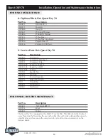
Page 15: ...unnecessarily on the defrost control FOR OWNER ROUTINE MAINTENANCE 8 Optional Parts List Quest Dry 70 Part No Description 4030671 Filter MERV 11 4030113 Pump Kit 4029908 Hang Kit 4023647 8 Gravity Da...

Page 16: ...erant during normal operation A flooded evaporator should maintain nearly constant pressure and temperature across the entire coil from inlet to outlet The mixture of gas and liquid refrigerant enter...

Page 17: ...10 Optional Condensate Pump Safety Switch open Unit Test to determine problem 1 Detach field control wiring connections from main unit 2 Connect the yellow and green pigtails from the main unit togeth...

Page 18: ...emain closed when the ventilation timer is not activated to prevent over ventilating the structure when the unit is dehumidifying or recirculating the indoor air The electric ventilation timer operate...

Page 19: ...present proof of purchase lease upon request by use of the warranty card receipt invoice or other reasonable and reliable means The end user is responsible for normal care This warranty only applies...

Reviews: