background image

1-866-413-5214

Quest Oil Fired CHH-980  Installation, Operation and Maintenance Instructions


17

quest

quest

www.QuestProtect.com

sales@QuestProtect.com

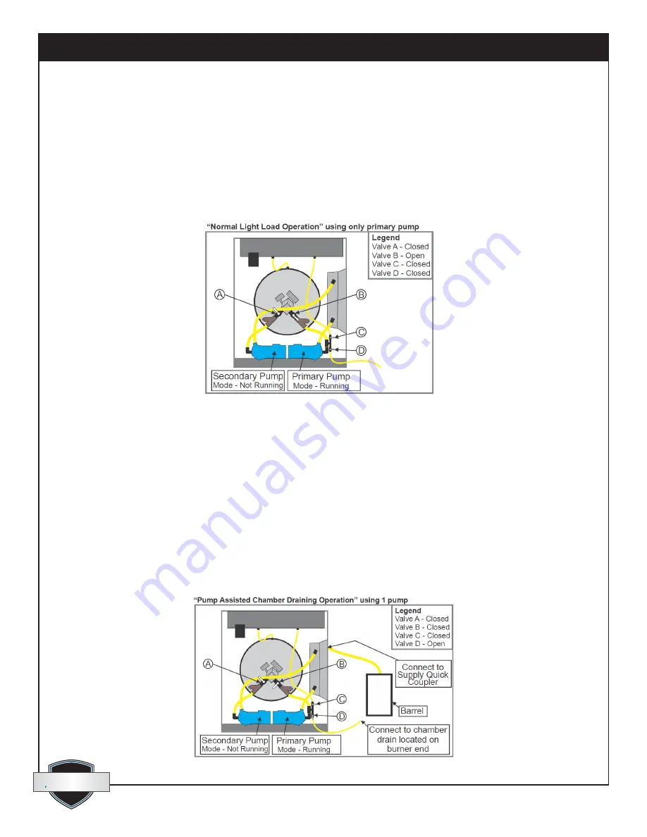
4.6 Normal 1-Pump Mode with Light Load:

•  If the CHH-980 is connected to a distribution system that will demand only half or less of its capacity 

in terms of flow requirements and heat draw, the “Normal 1-pump Mode” should be used. This will 
provide better efficiency for the lighter load.

•  Adjust the valves as shown in (Fig. 41). Turn ON only the “Primary Pump Switch” (Fig. 15).

•  Keep in mind that either pump could be used in this mode but it is imperative that the valve (A or B) for 

the pump not being used must be closed to prevent short circuiting of the fluid and greatly reduced out-
flow.

4.7 Pump-assisted Chamber Draining:

•  If, for any reason, the CHH-980 heat exchanger must be drained, the primary pump can be used to 

simplify the draining. 

•  Locate the 1/2” drainage hose, at the opposite end of the unit, below the burner. Connect this hose to 

the short ½” suction hose at valve “D” in (Fig. 42). Garden hose fittings make this connection easy. 
OPEN both valves on the 1/2” drainage line below the burner.

•  Prepare a short length of 1” hose with a female quick coupler on one end and the other end open. 

Connect the female quick coupler to one of the male outlets on the side of the CHH-980. The open end 
should be placed in a barrel to catch the fluid. It will take more than 100 gallon capacity to hold it all.

•  Adjust the valves as shown in (Fig. 42). Turn ON only the “Primary Pump Switch” (Fig. 15).

•  When all fluid is pumped out, shut OFF the pump switch.

41:Normal Mode with 1 Pump Operation.

42: Pump-assisted Chamber Drain.

Summary of Contents for PowerHeat 980 Pro CHH-980

Page 1: ...th a Blocked Flue shutoff device If any part of the flue gas passageway in the combustion chamber exhaust pipe or rain cap should become blocked or adversely restricted a pressure sensing switch Fig 27 pg 11 will break the electrical control circuit and not allow the burner to run There is a Manual Reset button on this switch that will have to be reset before re firing can occur If the burner fail...

Page 2: ...rols Electrical 9 3 8 Control Switches Gauges Identification 10 4 Setup 12 4 1 Positioning Equipment on the job 12 4 2 Hose Accessory Connections 12 4 3 Filling the Fluid System 15 4 4 Eliminating Air from the HTF Circuit 16 4 5 Normal 2 Pump Mode with Full Load 16 4 6 Normal 1 Pump Mode with Light Load 17 4 7 Pump assisted Chamber Draining 17 4 8 Oil Burner Installation and Setup 18 5 Operation 1...

Page 3: ...gers such as Fan coils for heating and drying of structures Multi circuit line heat exchange hose or tubing for ground thawing concrete curing snow melting and slab heating Custom hydronic heat exchange accessories and applications The CHH 980 oil fired units are equipped with a burner that will burn either of the following 2 standard grade light heating oil or diesel fuel 1 winter grade light hea...

Page 4: ...manently installed pressure gauge to simplify monitoring of oil pressure when setting up the burner Door handles and hose connection couplers for the external HTF circuits are recessed so as not to create snag points when moving shipping or delivering the unit 2 Safety 2 1 General Safety Guidelines CAUTION This is a fuel burning appliance Some surfaces will become extremely HOT When using oil or d...

Page 5: ...tion Use safety glasses First aid measures Eyes Flush eyes with plenty of water Skin Wash off in flowing water or shower Ingestion Induce vomiting if large amounts are ingested Consult medical personnel Inhalation Remove to fresh air if effects occur Consult a physician Note to physician No specific antidote Supportive care Treatment based on judgement of the physician in response to reactions of ...

Page 6: ...e USA by Wayne Combustion Systems 1 or 2 light heating oil or diesel fuel may be used A gauge is connected to a pressure tap port on the fuel pump of the burner to aid in setting the burner and monitoring performance A Fuel Filter is mounted to the burner pump inlet port Supply and return fuel lines are equipped with quick couplers for ease of connection to a fuel tank 4 CHH 980 Oil Burner 5 Oil P...

Page 7: ...Fig 28 See chart Fig 7 for specifications 8 Fluid circulation Pumps CHH 980 Wayne Burner Model FH Operational Mode ON OFF Electrical Characteristics V A Hz Ph 120 11 5 60 1 Nozzle Delavan Part 2 required 2 75 60 B Fuel Pump Pressure PSI Kpa 162 1117 Fuel Input Rate factory set USGPH Liters Hr 7 0 26 5 Heat Input based on 140 000 Btu per USG Btu H Kw H 980 000 287 Heat Output 80 net efficiency Btu ...

Page 8: ...e following HTF supply temperature HTF return temperature A digital hour meter Fig 12 logs system run time A series of 6 LED indicator lights Fig 18 illuminate in sequence as each of the following scenarios is proven 1 120 volt control power is present clear lens 2 HTF level is adequate in reservoir green lens 3 High temperature auto control has not interrupted the circuit green lens 4 High temper...

Page 9: ...Stat Electronic operating controller Fig 13 Main power disconnect Fig 14 Pump ON OFF switches Fig 15 Burner circuit ON OFF switch Fig 16 Glycol supply and return temperature gauges Fig 17 LED lights 120 Volt Fig 18 The following components are inside the UL approved panel Main system breaker Fig 19 Pump circuit breakers Fig 19 Burner circuit breaker Fig 19 Main power switch body Fig 20 Temperature...

Page 10: ...mounted on HTF reservoir Fig 24 Automatic reset High limit switch mounted in HTF plumbing circuit Fig 25 Manual reset High limit switch mounted in HTF plumbing circuit Fig 26 Manual reset High pressure switch Fig 27 3 8 Controls Switches Gauges Identification Mounted on Control Panel 12 Hour Meter 13 Stat Digital 14 Main Power Switch 15 Pump Switches 17 Glycol Temperature Gauges 18 LED Indicator L...

Page 11: ...nted Inside Control Panel Controls Mounted Remotely Pump Pressure and Oil Pressure Gauges 19 Circuit Breakers 20 Main Power Switch Body 21 Transformers for Digital Temp Gauges 22 Contactors 23 Terminal Blocks 24 Low Water Cutoff 25 Auto reset Temp Limit 26 Man reset Temp Limit 27 High Pressure Switch 28 Pump Pressure Gauge PSI 29 Oil Pressure Gauge PSI ...

Page 12: ...3 or multiple 5 8 hose circuits for ground thawing concrete curing slab heating or snow melting Fig 34 Use only approved hose as supplied by ThermaStor Otherwise compatibility issues may arise Hoses are pre charged with the recommended mixture of water and propylene glycol HTF and are equipped with hydraulic style quick couplers Every hose has a male connector on one end and a female connector on ...

Page 13: ...ution 1 Central Hydronic Heating Unit 2 Burner Heat Exchanger 3 Circulating Pump 4 Reservoir for Expansion Filling 5 Primary Fluid Hoses 1 6 Secondary Fluid Hoses 3 4 or 1 7 Manifold for Multiple Connections 8 Fancoil Heat Exchanger 9 Heat Transfer Coil 10 Air Moving Fan 11 Heated Supply Air 12 Intake Air 13 Hose Grid Line Heat Exchanger 5 8 14 Vapor Barrier 15 Insulated Tarps ...

Page 14: ...nce Instructions 14 www QuestProtect com sales QuestProtect com 33 Manifolds for Fancoils Supply Return 34 Manifold for Thaw Cure 35 HTF Level Gauge 37 HTF Circuit Valves Y strainers High Temp Limits 31 Hoses Connected to CHH 980 32 Fancoils Connected to CHH 980 Unit 36 Vented Filler Cap ...

Page 15: ...d as DowFrost Use of any other product that cannot be proven to be equal in all respects will void warranty of the system Check the HTF level gauge Fig 35 The reservoir should be to full when the system is cold Add approved fluid if necessary at the vented filler cap Fig 36 or use the pumping system to draw HTF from a pail or barrel If you prefer this method place the free open end of the suction ...

Page 16: ...f 35 to 40 PSI is observed at the glycol pressure gauge Fig 28 Once all air is eliminated turn the pump OFF and set the valve arrangement for normal operating mode Fig 40 or 41 below Check the HTF level again and top up if necessary 1 8 to 1 4 full See step 4 3 above 4 5 Normal 2 Pump Mode with Full Load If the CHH 980 is connected to a distribution system that will demand most of its capacity in ...

Page 17: ...ced out flow 4 7 Pump assisted Chamber Draining If for any reason the CHH 980 heat exchanger must be drained the primary pump can be used to simplify the draining Locate the 1 2 drainage hose at the opposite end of the unit below the burner Connect this hose to the short suction hose at valve D in Fig 42 Garden hose fittings make this connection easy OPEN both valves on the 1 2 drainage line below...

Page 18: ...itioned for Normal Single pump operation as in article 4 6 above Turn ON only the primary pump switch Fig 15 and check the pump pressure gauge Fig 28 Steady pressure around 35 to 45 PSI indicates that no air remains in the fluid circuit See article 4 4 above for rapid air removal Once a stable pump pressure is achieved turn ON the burner switch Fig 16 The following sequence should now occur Observ...

Page 19: ...rresponding pump is running 5 2 Shutdown Turn OFF the burner switch Fig 16 The burner will shut down but the circulation pump will continue to run It is recommended that the fluid be allowed to continue circulating until it has cooled down to 100ºF or lower Turn OFF both pump switches Fig 15 If any fancoils and hoses have been placed at a higher elevation than the CHH 980 the primary hoses should ...

Page 20: ... obstruction Clean if necessary a This check should be performed every time when putting the system into operation on a new project or a minimum of once yearly D After placing this unit in operation the low water safety shutoff device must be tested Must be performed by a trained service technician ONLY The low water cutoff switch is located in plain view at the same end of the CHH 980 as the circ...

Page 21: ...ly re set d By pushing the reset button located on the electrical box cover of the pressure switch the control will reset and the burner should light again e This control should be tested every time when putting the system into operation on a new project or a minimum of once yearly G Procedure for cleaning flue gas passageways This procedure should be performed in the event of blockage in the flue...

Page 22: ...pt clear and free from combustible materials gasoline and all other flammable vapors and liquids K At both ends of the CHH 980 cabinet Louvers are stamped into the access doors to provide intake air for combustion and ventilation Check on a daily basis to ensure that nothing is allowed to obstruct this free flow of air L Check heat transfer fluid level daily Maintain between 1 4 cold and 1 2 hot d...

Page 23: ...ner s Screens Examine all hoses and replace or repair any that are cracked or in any way damaged Lubricate all quick couplers with light oil Thoroughly Clean the system inside and out Examine The Flue gas exhaust pipe and Rain cap Clean as needed Check condensate drainage tube and clean if necessary Make certain that no flammable materials are anywhere near the heating unit Make certain that nothi...

Page 24: ...wer Light is ON indicates A Power is present through main switch The 2 digital temperature gauges should be ON If not use a multi meter to check the following a The 2 transformers Fig 21 should show 120VAC in and 6VDC out If power goes in but not out replace transformer b If there is 6VDC at the digital gauge but it does not illuminate replace the temp gauge B There is no power going through the l...

Page 25: ...0ºF and the digital stat maximum 200ºF b With the high temp limit switch re set and actual fluid temperature well below the set points of both high temp switches check with a multi meter for 120V in and out of the high temp limit switch Fig 26 If there is power in but not out replace the high temp limit switch 4 High Pressure Switch Light plus 1 2 3 are ON indicates A Fluid supply temperature is b...

Page 26: ... it still fails replace it B The burner goes to lockout after the prepurge period because the flame does not ignite a No fuel in tank or lines b Air has not been fully bled from the fuel lines c Check fuel lines The smallest leak will allow air to enter and prevent ignition d The fuel filter is dirty Replace filter e Nozzle is plugged Replace nozzle f The spark is irregular or not present Re align...

Page 27: ...1 866 413 5214 Quest Oil Fired CHH 980 Installation Operation and Maintenance Instructions 27 quest quest www QuestProtect com sales QuestProtect com 7 3 Electrical Schematics ...

Page 28: ...quest quest 1 866 413 5214 Quest Oil Fired CHH 980 Installation Operation and Maintenance Instructions 28 www QuestProtect com sales QuestProtect com ...

Page 29: ...1 866 413 5214 Quest Oil Fired CHH 980 Installation Operation and Maintenance Instructions 29 quest quest www QuestProtect com sales QuestProtect com Wayne FH Burner ...

Page 30: ...ification unauthorized or improper repair or installation accident acts of nature or any other cause beyond Therma Stor LLC reasonable control Limitations and Exclusions If any Quest CHH 980 part is repaired or replaced the new part shall be warranted for only the remainder of the original warranty period applicable thereto but all warranty periods will be extended by the period of time if any tha...

Reviews: