background image

- 4 - 

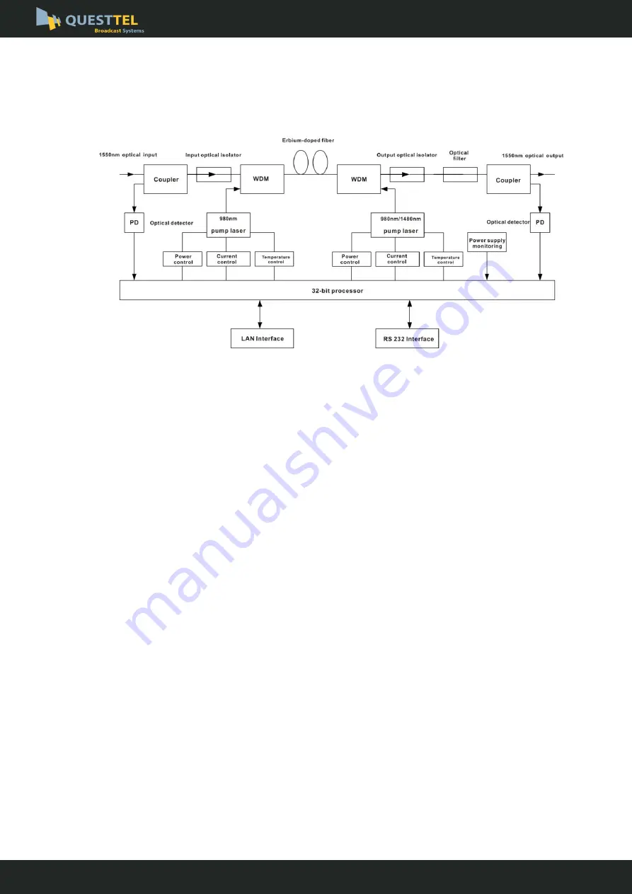
3. Block diagram

4. Technique Parameter

4.1 Link test conditions


Special  instructions:

  The  performance  parameters  of  this  manual  according  to  the 

measuring method of GY/T 184-2002 < CATV system analog optical fiber amplifier 
technical  requirements  and  measuring  method>,  and  tested  in  the  following 
conditions.   

Test  condition:

  With  standard  optical  fiber  and  standard  optical  receiver  composed 

the  test  link.  Set  59  PAL-D  analog  TV  channel  signal  at  550MHz  frequency  range 
under the specified link loss. Transmit digital modulation signal at range of 550 MHz 
~ 862MHz, the digital modulation signal level (in 8 MHz bandwidth) is  10dB lower 
than  analog  signal  carrier  level.  When  the  input  optical  power  of  optical  receiver  is 
-1dBm, measure the C/CTB, C/CSO and C/N. 

www.questtel.com

sales@questtel.com

EDFA Optical Amplifier

 User Manual


L-RF-EDFA-18dBm

Summary of Contents for L-RF-EDFA-18dBm

Page 1: ...L RF EDFA 18dBm User Manual CATV EDFA Optical Amplifier 1550nm 18dBm www questtel com sales questtel com...

Page 2: ...5 5 External Function Description 6 5 1 Front Panel Description 6 5 2 Rear Panel Description 7 5 3 Displayed Parameter description 8 6 Installation debugging 12 6 1 Unpack and Check 12 6 2 Instruments...

Page 3: ...le the fiber amplifier is working there is an invisible laser beam from the optical output adapter on the front panel Avoiding permanent harm to the body and eye the optical output should not aim at t...

Page 4: ...is adjustable attenuation range is 0 3dB Adopt high performance erbium doped fiber high efficiency energy conversion Adopt advanced 32 bit processor coordinate with perfect automatic monitoring syste...

Page 5: ...on With standard optical fiber and standard optical receiver composed the test link Set 59 PAL D analog TV channel signal at 550MHz frequency range under the specified link loss Transmit digital modul...

Page 6: ...turn loss Input dB 45 Output dB 45 Pump leakage power Input dBm 30 Output dBm 30 Optical connector type FC APC or SC APC Power supply voltage V AC160V 250V 50 Hz Consumption W 30 Operating Temperature...

Page 7: ...ormal 4 Output optical power indicator This light turns on when the output optical power is large than 10dBm 5 160 32 Dot matrix LCD screen used to display all the parameters of the machine 6 Display...

Page 8: ...ng normal So the port should not be aligned to the human body or the naked eyes to avoid accidental injury 4 RS232 interface Used for configuring the network management parameters 5 LAN interface corr...

Page 9: ...p1 Temper xx x C Temperature of pump1 accurate to 0 1 C Pump1 Tec x xx A Cooling current of pump1 accurate to 0 01 A Pump2 Bias x mA Bias current of pump2 accurate to 1m A Pump2 Temper xx x C Temperat...

Page 10: ...e factory configuration set content as shown above 3 Alarm Status Input Status xxx xxx LOLOW Very low input optical power alarm xxx LOW Low input optical power alarm xxx HIGH High input optical power...

Page 11: ...rm xxx LOW Low bias current of pump2 alarm xxx HIGH High bias current of pump2 alarm Xxx HIHIGH Very high bias current of pump2 alarm Pump2 Temper xxx xxx LOLOW Very low temperature of pump2 alarm xxx...

Page 12: ...W Low 5V DC power supply alarm xxx HIGH High 5V DC power supply alarm Xxx HIHIGH Very high 5V DC power supply alarm Device Temper xxx xxx LOLOW Very low chassis temperature alarm xxx LOW Low chassis t...

Page 13: ...ably grounding The grounding resistance must be 4 3 Use the digital multimeter to check the supply voltage make sure the supply voltage comply with the requirements and the switch key is on the OFF po...

Page 14: ...it 1 2 minutes after wash let the connector surface dry in the air 3 Cleaned optical connector should be connected to optical power meter to measure optical output power to affirm whether it has been...

Page 15: ...put power will decrease rapidly And turn the active optical fiber connector slightly the optical output power changes obviously c Please operate the optical fiber under the condition of shut off the p...

Page 16: ...ck 7 Object and Liquid Entry Never push objects of any kind into this product through openings as they may touch dangerous voltage points or short out parts resulting in a fire or electric shock Never...

Reviews: