13
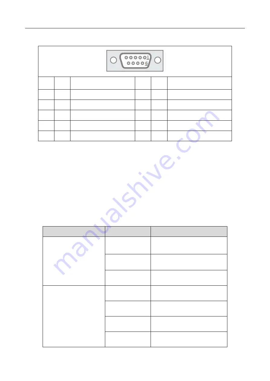
3.4.1 Pins Instruction of DB9
Item
Pins
Function
Item
Pins
Function
1
9P-1
No connection
6
9P-6
No connection
2
9P-2
TX(Transmitter signal )
7
9P-7
2-485A
3
9P-3
RX(Receiver signal)
8
9P-8
2-485B
4
9P-4
No connection
9
9P-9
No connection
5
9P-5
GND(power supply “0V”)
3.5 Instruction of Input & Output
The following input interfaces and output interfaces are corresponding to the signal pins which are defined as
“Min, Mout, Ein, Eout” at the above socket. Also, it is corresponding to the interface at the “IO Test”
displaying window.
After setting, it can test the function of IO interface at the “IO Test” displaying window.
The interfaces in following table can be set at the “Input Config” or “Output Config” of “System Config 2”
of teaching pendant. It can define the special function for the following input & output interfaces which are
corresponding to the above sockets.
Main board port defined functions are listed in following table:
Board
Port
Function
Expansion input port
Ein12
Block material alarm signal
Ein13
Lack material alarm signal
Ein14
Temperature alarm signal
Main input port
Min1
Reset key signal
Min2
Emergency stop key signal
Min3
Safety signal
Min4
Start/pause key signal


