QUICK BGA EA-H00 OPERATION MANUAL
Page 21
Only when communicate state is online, we can control equipment auto carry out flow
by software.
Working area: contain every working button “heat arm up”, “heat arm down”,“dissipation
open/dissipation close”,“cooling fan enter ” , “cooling fan out”.
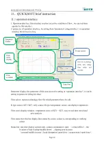
11.2 parameter testing interface
Parameter testing interface: when solder or desolder new chip, by this display ,we can do solder or desolder
testing.
Counterpoint height: memory setting height. After setting, auto memory this height, the
same specification chip counterpoint, call save flow, do not need adjust
counterpoint height.
Counterpoint height cancel: cancel saved counterpoint height.
Suck height: memory sucking height which have be set. After setting, auto memory this
height, when suck the same chip next time, we can call the saved flow, not
need adjust counterpoint height.
Cancel suck height: cancel suck height which have be saved.
In flow edit display, show goal flow name and technology type
(
desolder/solder
)
、
nozzle
size
、
down distance and heat dissipation air quantity etc.
Down distance: adjust heat head height range, setting range 0~255mm; heat dissipation air
quantity setting range 35~100. (can adjust on the basis of PCB adjust)
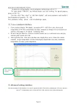
After edit parameter in parameter setting display, in“flow edit display”input flow name,
appropriate nozzle size, select flow technology curve is “desolder”
、
or “solder”. And then click
“parameter save”
、
“save curve”
,
can save current parameter and flow curve.
Parameter
testing
display
Flow
edit
display
Flow
curve
display

