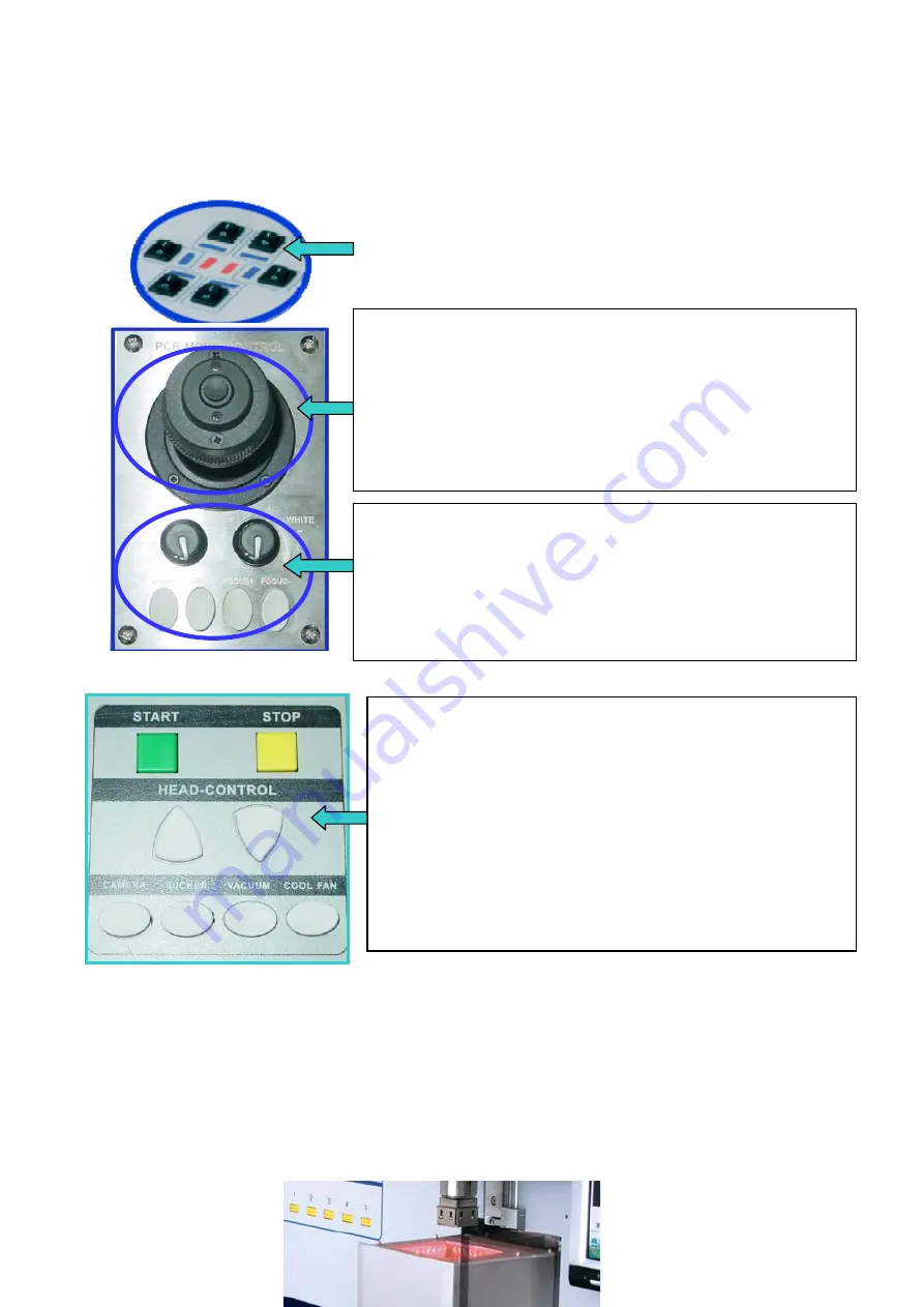
*Keys on the right side
1.
Press the key on the top of the rocker “PCB MOVE CONTROL”
and when swinging the rocker leftward or rightward, the PCB fixture
will do the corresponding movement, leftward or rightward. When
swinging the rocker onward or backward, the PCB fixture will do
the corresponding movement, onward or backward.
2.
If do not press the key on the top of the rocker and swing the rocker,
the pad sucking the chip can do turn 360
°
.
1.
Only when the aligning arm is out, the boons “RED”& “WHITE”
and the keys “ZOOM” & “FOCUS” can work.
2.
The “WHITE” knob adjusts the brightness of the bottom white light.
3.
The “RED” knob adjusts the brightness of the top red light.
4.
“ZOOM+”&“ZOOM-” keys zoom the image.
5.
“FOCUS+” & “FOCUS-” for camera focusing.
Infrared heater switch: controlling the corresponding heater is on
or off. The middle two heaters (red mark) are on.
1.
START
: in standby mode, click it into the soldering or
de-soldering process.
2.
STOP
: in the soldering or de-soldering process, click it to exit the
current process and the heating arm will move upwards.
3.
HEAD-CONTROL
△ ▽
: Control the movement of the top
sirocco-heating arm, upward or downward.
4.
CAMERA
: Click it to make the aligning arm moving out and
open the camera. It can do the alignment.
5.
SUCKER
: Make the sucking pad suck the chip.
6.
VACUUM
: Click it to open the vacuum bump.
* Note: In the flow of soldering or de-soldering, the keys (CAMERA, SUCKER, VACUUM and COOL
FAN) cannot work.
7. Aligning
Arm Instruction
Aligning arm is used for the element alignment. In the aligning arm, there is a camera which transmitting the
information by video cord and then displaying the image about the soldering point in the PCB and element
pins below the nozzle. Users can observe element alignment by adjusting function keys.
Page 7
Summary of Contents for BGA2100
Page 1: ...QUICK BGA 2100 ...


