background image

15

INSTALLATION

GB

DYLAN DH 1500/1700/2000W  - REV001A

WARNING:

 before wiring up, be sure the electrical cables are not live.

BEFORE USING THE WINDLASS READ THESE INSTRUCTIONS CAREFULLY.
IF IN DOUBT, CONTACT YOUR NEAREST “QUICK

®

” DEALER.

WARNING:

 the Quick

®

  windlasses  are  designed  to  weigh  the  anchor. 

 Do not use the equipment for other purpo-

ses. 

 Quick

®

 shall not be held responsible for damage to equipment and/or personal injury, caused by a faulty use

of the equipment. 

 The windlass is not designed for the loads that might occur in extreme weather conditions (storms). 

 Always deactivate the windlass when not in use. 

 Check that there are no swimmers nearby before dropping anchor. 

 The splice between the rope and the chain must be tightly woven for the rope to slide easily into the gypsy shape. For any 

problem or request, feel free to contact Quick

®

 Technical Service. 

 For improved safety we recommend installing at least 

two anchor windlass controls in case one is accidentally damaged. 

 We recommend the use of the Quick

®

 hydraulic-ma-

gnetic switch as the motor safety switch. 

 Secure the chain with a further device before starting the navigation. 

 The contactor unit or reversing contactor unit must be installed in a point protected from accidental water contact. 
 After completing the anchorage, secure the chain or rope to fi xed points such as chain stopper or bollard. 
 To prevent accidental releases, the anchor must be secured. The windlass shall not be used as the only securing device. 
 Isolate the windlass from the power system during navigation (switch the circuit breaker off) and lock the chain securing it to 

a fi xed point of the boat. 

THE PACKAGE CONTAINS:

 windlass (on deck unit + motorgearbox) - contactor unit - base gasket - drill template - handle - bolts and 

screws (for assembly) - user’s manual - conditions of warranty.

TOOLS REQUIRED FOR INSTALLATION:

 drill and drill bits: Ø 5 mm (3/16”), Ø 9 mm (23/64”) and Ø 11 mm (7/16”) - Ø 80 mm (3" 9/64)  

hollow mill; hexagonal wrenche: 13 mm.

“QUICK

®

”ACCESSORIES RECOMMENDED:

 anchoring RL control board (mod. 800) - Waterproof hand helds R/C (mod. HRC1002) 

- Foot switch (mod. 900) - Hydraulic-magnetic circuit breaker - Anchor chain counter (mod. CHC1102M and CHC1202M) - Radio control 
RRC (mod. R02, PO2, H02).

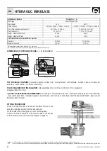
INSTALLATION REQUIREMENTS:

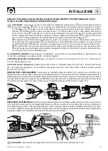
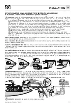
 the windlass must be positioned with the gypsy aligned with the bow roller. Ensure that the 

upper and lower surfaces of the deck are as parallel as possible. If this is not the case, compensate the difference appropriately (a lack 
of parallelism could result in a loss of motor power). The deck thickness must be included among the fi gures listed in the table. In cases 
of other thicknesses it is necessary to consult a Quick

®

 retailer. There must be no obstacles under deck to the passage of cables, rope 

and chain; lack of depth of the peak could cause jamming.

FITTING PROCEDURE:

 when the ideal position has been established, drill four holes using the drilling template provided.

Remove excess material from the chain passage, refi ne and fl atten with a specialized product (marine paint, gel coat or two pack epoxy) 
to assure free passage for both rope and chain. Position the upper section, inserting the gasket between the deck and the base and 
connect the lower section to the assembly, inserting the shaft into the reduction unit. 
Fix the windlass by screwing the nuts onto the fi xing studs. Connect the supply cables from the windlass to the contactor unit.

PAINT

40 cm 

(16”)

Max 

5 mm

(3/16”)

45°

90°

90°

90°

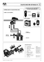
Summary of Contents for DYLAN DH

Page 1: ...REV 001A High Quality Nautical Equipment Manuale d uso SALPA ANCORA VERTICALI User s Manual VERTICAL WINDLASSES DYLAN DH DH 1512 DH 1512 D DH 1712 DH 1712 D DH 1724 DH 1724 D DH 2024 DH 2024 D IT GB...

Page 2: ......

Page 3: ...importanti Pag 8 9 Schema di collegamento trifase Pag 10 11 Salpa ancora idraulico Pag 12 13 Manutenzione Pag 14 15 Set INDICE INDEX IT GB Pag 16 Technical data Pag 17 Installation Pag 18 Connection...

Page 4: ...na secondo il sistema Quick BARBOTIN 10 mm 3 8 12 13 mm Catena supportata 10 mm 10 mm 3 8 3 8 13 mm 12 mm 7 16 DIN 766 ISO G4 BBB DIN 766 ISO G4 Cima supportata 5 8 3 4 3 4 MODELLO DYLAN DH D POTENZA...

Page 5: ...c care la catena ad un punto fisso dell imbarcazione LA CONFEZIONE CONTIENE salpa ancora top motoriduttore cassetta teleruttori guarnizione della base dima di foratura leva viterie per l assemblaggio...

Page 6: ...lla pag 4 CASSETTA TELERUTTORI MOD T6315 12 12V MOD T6315 24 24V C A2 PULSANTI A PIEDE MOD 900U E 900D NERO MARRONE BLU MARRONE NERO BLU A1 FUSIBILE 4A 12V 2A 24V L L1 L2 L3 L4 L4 L2 L3 L1 L3 SCHEMA D...

Page 7: ...e la leva in senso orario Per calare l ancora elettricamente occorre premere il pulsante DOWN del comando a vostra disposizione In questo modo la calata perfettamente controllabile e lo svolgimento de...

Page 8: ...CHC1102 M CONTACATENA PER ANCORAGGIO MOD CHC1202 M DOWN UP BLU MARRONE NERO BLU MARRONE NERO DOWN SENSORE UP CAN H CAN L GRIGIO ROSSO VERDE MARRONE BIANCO BLU NERO BLU MARRONE NERO 150 CAN H CAN L CA...

Page 9: ...CONTACATENA A PULSANTIERA MOD CHC1102 M CONTACATENA PER ANCORAGGIO MOD CHC1202 M DOWN UP BLU MARRONE NERO BLU MARRONE NERO DOWN SENSORE UP CAN H CAN L GRIGIO ROSSO VERDE MARRONE BIANCO BLU NERO BLU MA...

Page 10: ...700W 41 39 38 40 37 36 6 7 75 15 12 2 3 4 8 10 13 14 28 27 25 29 31 30 32 33 34 18 16 19 21 5 5 5 5 5 9 11 35 42 23 23 23 23 20 22 17 16 1 24 26 50 51 52 53 54 55 56 49 48 47 46 70 44 45 46 43 44 45 7...

Page 11: ...morsetteria sup PCCPPMMR2000 68 Vite autofilettante M3 9x22 MBV03922AXCC 69 Vite autofilettante M3 9x32 MBV03932AXCC 70 Guarniz flangia ridut TOP TG60 PGFLRDTG6000 71 Guarniz flangia ridut TOP TG70 PG...

Page 12: ...leva viterie per l assemblaggio manuale di istruzioni condizioni di garanzia ATTREZZI NECESSARI PER L INSTALLAZIONE trapano con punta 12 mm 15 32 a tazza 90 mm 3 1 2 chiave esagonale 17 mm ACCESSORI...

Page 13: ...ILE PULSANTIERA RICEVITORE ACCESSORI QUICK PER L AZIONAMENTO DEL SALPA ANCORA IDRAULICO TRASMETTITORI RADIOCOMANDI POS DENOMINAZIONE CODICE 47 Grower 8 inox MBG08X000000 60 Riduttore 2000W serie Quick...

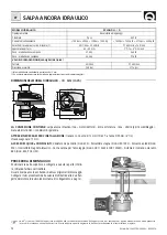
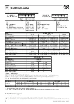
Page 14: ...rope with a rope chain splice manufactured with the Quick system GYPSY 10 mm 3 8 12 13 mm Chain size 10 mm 10 mm 3 8 3 8 13 mm 12 mm 7 16 DIN 766 ISO G4 BBB DIN 766 ISO G4 Rope size 5 8 3 4 3 4 MODEL...

Page 15: ...to a fixed point of the boat THE PACKAGE CONTAINS windlass on deck unit motorgearbox contactor unit base gasket drill template handle bolts and screws for assembly user s manual conditions of warranty...

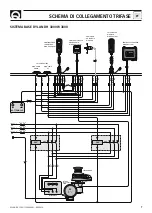
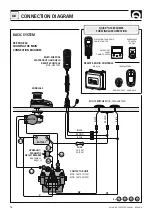
Page 16: ...see table on page 12 CONTACTOR UNIT MOD T6315 12 12V MOD T6315 24 24V C A2 FOOT SWITCHES MOD 900U AND 900D BLACK BROWN BLUE BROWN BLACK BLUE A1 FUSE 4A 12V 2A 24V L L1 L2 L3 L4 L4 L2 L3 L1 L3 CONNECTI...

Page 17: ...the water To slow down the chain the handle must be turned clockwise To cast the anchor by using the electrical power press the DOWN button on the control pro vided In this manner anchor casting is un...

Page 18: ...ARD THREE PHASE CONNECTION DIAGRAM SENSOR WATERTIGHT HAND HELD CHAIN COUNTER MOD CHC1102 M WATERTIGHT PANEL CHAIN COUNTER MOD CHC1202 M DOWN UP BLUE BROWN BLACK BLUE BROWN BLACK DOWN SENSOR UP CAN H C...

Page 19: ...380V CA Max 5 5KW TERMINAL BOARD SENSOR WATERTIGHT HAND HELD CHAIN COUNTER MOD CHC1102 M WATERTIGHT PANEL CHAIN COUNTER MOD CHC1202 M DOWN UP BLUE BROWN BLACK BLUE BROWN BLACK DOWN SENSOR UP CAN H CAN...

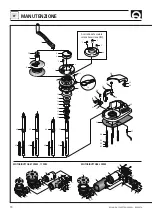
Page 20: ...700W Provided in the box only in the version D 41 39 38 40 37 36 6 7 75 15 12 2 3 4 8 10 13 14 28 27 25 29 31 30 32 33 34 18 16 19 21 5 5 5 5 5 9 11 35 42 23 23 23 23 20 22 17 16 1 24 26 50 51 52 53 5...

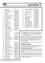
Page 21: ...8 Self tapping screw M3 9x22 MBV03922AXCC 69 Self tapping screw M3 9x32 MBV03932AXCC 70 Gearbox flange gasket Top TG60 PGFLRDTG6000 71 Gearbox flange gasket Top TG70 PGFLRDTG7000 72 O ring bush PGR031...

Page 22: ...ons of warranty TOOLS REQUIRED FOR INSTALLATION drill and drill bits 12 mm 15 32 90 mm 3 1 2 hollow mill hexagonal wrenche 17 mm QUICK ACCESSORIES RECOMMENDED anchoring RL control board mod 800 Waterp...

Page 23: ...LD CHAIN COUNTER RECEIVER TRANSMITTERS REMOTE RADIO CONTROLS HANDHELD RADIO POCKET 62 78 81 82 47 83 82 79 80 60 47 61 POS DESCRIPTION CODE 47 Grower 8 stainless steel MBG08X000000 60 Gearbox 2000W Qu...

Page 24: ...INDLASSES CONTROL BOARD MOD 800 MOD 900 D DOWN FOOT SWITCH MOD 900 U UP L L1 L2 L3 L4 SENSOR MOTOR BATTERY c A2 A1 L4 L3 L2 DOWN UP BLUE BROWN BLACK BLUE BROWN BLACK DOWN SENSOR UP CAN H CAN L GREY RE...

Page 25: ...170 6 3 4 180 7 87 3 1 2 105 4 1 4 277 10 59 64 118 4 5 8 189 5 7 29 64 244 9 39 64 87 3 1 2 105 4 1 4 277 10 59 64 118 4 5 8 189 5 7 29 64 480 18 57 64 158 6 7 32 309 5 12 3 16 170 6 3 4 180 7 87 3...

Page 26: ...NOTE NOTES NOTES NOTIZEN NOTAS...

Page 27: ......

Page 28: ...ngipane 120 A 48124 Piangipane RAVENNA ITALY Tel 39 0544 415061 Fax 39 0544 415047 www quickitaly com E mail quick quickitaly com Codice e numero seriale del prodotto Product code and serial number GB...

Reviews: