background image


Table of Contents 

1.


Summary

…………………………………………………………………………………………………

2.


Specification and Technical Parameter

……………………………………………………………………


2.1 Specification

…………………………………………………………………………………………


2.2 Technical Parameter

…………………………………………………………………………………

3.


Product picture

……………………………………………………………………………………………

4.


Safety Instruction

…………………………………………………………………………………………

5.


Install the unit and use parts   

……………………………………………………………………………


5.1 Place the unit

…………………………………………………………………………………………


5.2 Check the unit

………………………………………………………………………………………


5.3 Connect the unit

………………………………………………………………………………………


5.4 Using parts

……………………………………………………………………………………………

6.


Keyboard and parameter setting

…………………………………………………………………………


6.1 Keyboard

…………………………………………………………………………………………


6.2 Parameter setting

……………………………………………………………………………………

A.


Input Password

………………………………………………………………………………………

B.


Modify working flow

…………………………………………………………………………………

C.


Modify working mode

…………………………………………………………………………………

C-1. Modify Parameter of working flow

…………………………………………………………………

D.


Modify laser alignment mode

………………………………………………………………………

13 

E.


System instruction

……………………………………………………………………………………

13 

7.


Technics Instruction

………………………………………………………………………………………

14 


7.1 Soldering Technics

…………………………………………………………………………………

14 


7.2 De-soldering Technics

………………………………………………………………………………

15 

8.


Turn off the system

……………………………………………………………………………………

15 

9.


System Maintenance

……………………………………………………………………………………

16 


Summary of Contents for QUICK2035

Page 1: ...you for purchasing our Rework System The system is exclusively designed for reworking and soldering SMD component Please carefully read this manual before operating the system Store this manual in a...

Page 2: ...eck the unit 4 5 3 Connect the unit 4 5 4 Using parts 5 6 Keyboard and parameter setting 6 6 1 Keyboard 6 6 2 Parameter setting 7 A Input Password 7 B Modify working flow 8 C Modify working mode 9 C 1...

Page 3: ...ng controlled by closed loop ensures the precise and smaller technological window even heat distribution and appropriate peak value of temperature for lead free soldering The infrared heating tube of...

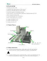
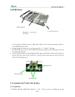
Page 4: ...eating time rising from T1 to T2 S2 Heating time rising from T2 to T3 S3 Heat preservation time of T3 3 Product Picture Top infrared heater Cooling fan PCB supporting bar Before and after the fixed mo...

Page 5: ...rts are in good condition and they aren t missed QUICK2035 Main unit IR Base plate with PCB Fixture Optional Power cord Operation Manual IRsoft Disc RS232 cable External cooling fan Optional Monitor O...

Page 6: ...ovable PCB fixture is able to fix PCB with different size Screwing down the Lock Knobs to fix PCB by locking PCB Fixed Bar 4 Unscrew PCB Lock Knobs and push Sliding Blocks by hand to open PCB Fixed Ba...

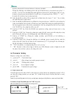
Page 7: ...F Function of START key During the standby condition make BGA IR get into soldering or de soldering situation G Function of Delay Key During the soldering or de soldering process pressing this key mak...

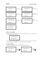
Page 8: ...his mode as long as this method can enter a new password If the amendments to the success of the show Saving Password Any key return 2 If the next step to modify the workflow the specific operation su...

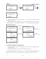
Page 9: ...stance Modify the working flow and make it become 1 flow Press Press SET password select 1 type solder select 1 Press Press OK select 1 type desolder select 1 type solder select 1 type desolder C 1 Mo...

Page 10: ...ldering When the temperature reaches T2 the temperature equably rises to T3 with a definite raising speed The soldering or de soldering will be finished when the temperature reaches to the peak value...

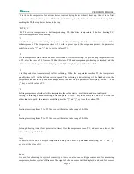
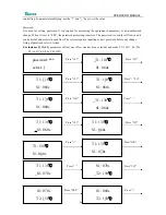
Page 11: ...ystem requires inputting correct password before any change Using of password refer to A item For instance Modify parameter of flow one Flow one has been selected and make T1 130 S1 70s T2 160 S2 50s...

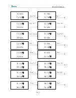
Page 12: ...s T2 160 S2 030s Press two times Press OK T2 160 S2 050s T2 160 S2 030s Press Press S2 050s T3 200 T2 160 S2 050s Press Press S3 010s TL 183 T3 200 S3 010s Press SET Press SET TL 183 TB 140 TL 183 TB...

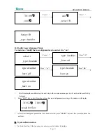
Page 13: ...laser off type desolder laser on 1 After finishing the modification the next step is the communication speed will not be able modified by keyboard 2 Press EXIT key to exit Now the system has saved all...

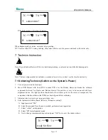
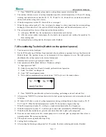
Page 14: ...r switch of each part 2 Move PCB Fixture with fixed PCB to make PCB over the Bottom Heater and make the soldered component between Top Heater and Bottom Heater The position is easy to be measured with...

Page 15: ...make the red laser point in the center of component 3 Adjust aperture system to get a proper window size 4 Select parameter with keyboard Refer to Parameter setting A Input password 000 B Select the...

Page 16: ...equipment please use parts provided by original factory Note After cutting off the power supply the housing is still very hot so please don t use any dangerous or combustible solvent to clean it Clea...

Reviews:

Related manuals for QUICK2035