OPERATION MANUAL
2.2 Technical Data
TL: Melting temperature of solder
T1: Heat preservation starting temperature of reflow soldering
T2: Heat preservation ending temperature of reflow soldering
T3: Peak value temperature of soldering and de-soldering
T0: Valve temperature: The lowest temperature of bottom heater when top heater heats up. T0<TB
TB: The set temperature of bottom heater
Tb: The real time temperature value of bottom heater
TC: The real time temperature value of top heater
S1: Heating time rising from T1 to T2
S2: Heating time rising from T2 to T3
S3: Heat preservation time of T3
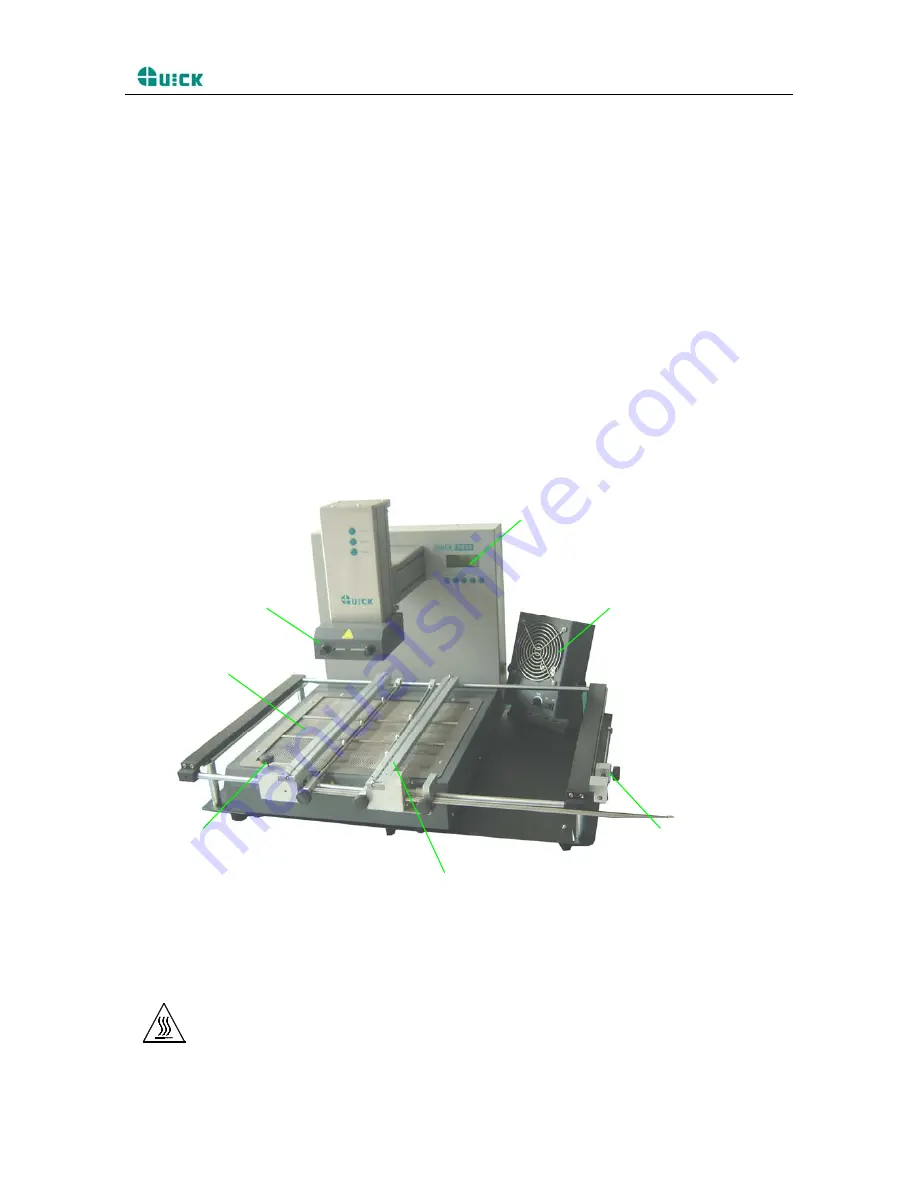
3. Product Picture
Top infrared heater
Cooling fan
PCB supporting bar
Before and after the
fixed-mobile frame knob
PCB lock knob
Bottom infrared heater
Display
4. Safety Instructions
Note: For safety of system and operator, please read this manual carefully before operating the unit.
Please note that the unit is suitable for soldering and de-soldering of electronic components.
Note: Top and bottom IR heater will be very hot during working, so explosive and combustible object or gas
and solvent is strictly prohibited in working areas, also please don’ touch the hot housing parts.
Page 2


