24
OPERATING
GB
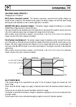
OPERATION
When the battery charger is switched on, all the LEDS on the front panel will light up for a short period. After
that the battery charger will place itself in the optimum charging mode to best suit the batteries or load
connected.
The battery charger has a loading characteristic of the IU
0
U type.
The SBC battery chargers can also be used as a power supply, that is, with batteries disconnected.
We suggest you use the battery charger in this mode only occasionally and not for ordinary use. However,
avoid connecting high inductive loads (e.g. high powered motors) with the batteries disconnected as it you
could cause damage to the equipment.
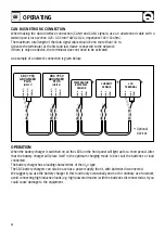
CAN BUS NETWORK CONNECTION
When making the data interface connection (CANH and CANL signals) use an unscreened cable with a
twisted pair (cross-section 0.25/ 0.35 mm
2
AWG 22/24, impedance 100/150 ohm).
The maximum total length of the data signal cable should be no more than 100 m.
Activate the terminator at the first and last device connected to the network.
If there is only one device, the terminator does not need to be activated.
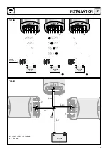
An example of a network connection is given below:
CAN-H(7)
CAN-L(2)
TERM(1)
CAN-H
CAN-L
TERM
CAN-H
CAN-L
TERM
CAN-H
CAN-L
TERM
CAN-H(7)
CAN-L(2)
TERM(1)
*
Optional
devices.
*
TEMPERATUR
BATTERIES
SENSOR
CURRENT
SENSOR
LCD
TERMINAL
SBC 1950
ADVANCED
PLUS
(Unit 1)
SBC 1950
ADVANCED
PLUS
(Unit 2)
*
*


