background image

11

INSTALLATION

GB

TOTEM 600/1000/1100 - REV005A

WARNING:


before wiring up, be sure the electrical cables are not live.

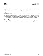
BEFORE USING THE CAPSTAN READ THESE INSTRUCTIONS CAREFULLY.
IF IN DOUBT, CONTACT YOUR NEAREST “QUICK

®

” DEALER.

WARNING:

 the Quick

®

 capstans are designed to weigh engineered for capstan operation. 

 Do not use the equipment for other purposes. 
 Quick

®

 shall not be held responsible for damage to equipment and/or personal injury, caused by a faulty use of the equip-

ment. 

 The capstan is not designed for the loads that might occur in extreme weather conditions (storms). 
 Always deactivate the capstan when not in use. 
 For improved safety we recommend installing at least two anchor capstan controls in case one is accidentally damaged. 
 We recommend the use of the Quick

®

 hydraulic-magnetic switch as the motor safety switch. 

 The contactor unit or reversing contactor unit must be installed in a point protected from accidental water contact.

THE PACKAGE CONTAINS:


capstan - reversing contactor unit - base gasket - handle - bolts and screws (for assembly) - 

drill template - user’s manual - conditions of warrant.

TOOLS REQUIRED FOR INSTALLATION:

 drill and drill bits: Ø 5 mm (13/64”), Ø 9 mm (23/64”) and Ø 10 mm (13/32”) - Ø 108 mm 

(4"1/4) hollow mill; hexagonal wrenches: 10 mm and 13 mm.

“QUICK

®

”ACCESSORIES RECOMMENDED:


anchoring RL control board (mod. 800) - Waterproof hand helds R/C (mod. HRC1002) 

- Foot switch (mod. 900) - Hydraulic-magnetic circuit breaker - Radio control RRC (mod. R02, P02, H02). 

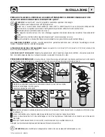
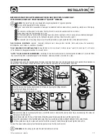
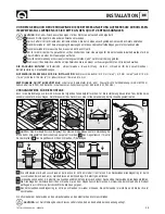
ASSEMBLY PROCEDURE 

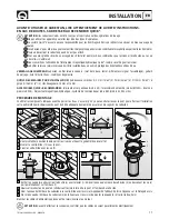
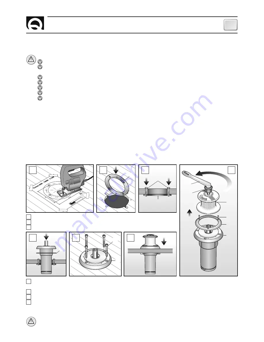
The following parts are to be checked before the holes are drilled. There must be no obstacles below deck to perform the installation in 
the lower part. The thickness of deck must be such as to allow the capstan to be securely placed in position. 

A

 Once the best position has been determined, drill the holes by using the drilling template.

B

 Install the back-flange (10) below deck.

C

 Secure the back-flange by using the screws (9).

D

 Remove the coupler (3) by releasing the bush (2) with the lever (1). Remove the capstan base ring (5) by loosening the screws (4) 

that secure it to the base (7).

E

  Lower the capstan from the top of the deck by fitting the gasket (8) between the deck and the capstan base.

F

  Secure the capstan base to the back-flange by using the screws (6). Apply a medium-strength adhesive to the screw threads. 

G

 Put the capstan base ring (5) in place and secure it with the screws (4). Install the coupler (3) and tighten the bush (2).  

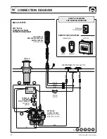
Connect the power cables coming from the reversing contactor unit to the electric motor. 

A

C

D

E

F

G

B

3

2

1

5

7

4

10

6

10

9

7

8

Summary of Contents for Totem 600

Page 1: ...Equipment Manuale d uso VERRICELLI DA TONNEGGIO User s Manual WARPING CAPSTANS Manuel de l utilisateur CABESTANS Benutzerhandbuch VERHOLWINDEN F R LEINE Manual del usuario WINCH DE TOAJE TOTEM TM 600...

Page 2: ...2...

Page 3: ...e Pag 16 Caract ristiques techniques Pag 17 Installation Pag 18 Sch ma de cablage Pag 19 Utilisation Avvertissements importants Pag 20 21 Entretien Seite 22 Technische Eigenschaften Seite 23 Montage S...

Page 4: ...ana Sezione minima cavi motore 3 Interruttore di protezione 4 Spessore coperta 5 Peso 1 Dopo un primo periodo d uso 2 Misure effettuate considerando il diametro della campana 3 Valore minimo consiglia...

Page 5: ...izioni di garanzia ATTREZZI NECESSARI PER L INSTALLAZIONE trapano con punte 5 mm 13 64 9 mm 23 64 e 10 13 32 a tazza 108 mm 4 1 4 chiavi esagonali 10 mm e 13 mm ACCESSORI QUICK CONSIGLIATI deviatore d...

Page 6: ...DRAULICO vedi tabella pag 4 CASSETTA TELEINVERTITORI MOD T6415 12 12V MOD T6415 24 24V C A2 PULSANTI A PIEDE MOD 900U E 900D NERO MARRONE BLU MARRONE NERO BLU A1 FUSIBILE 4A 12V 2A 24V L L1 L2 L3 L4 L...

Page 7: ...nella campana ATTENZIONE Quick consiglia di utilizzare un interruttore specifico per correnti continue DC e ritardato magneto termico o magneto idraulico per proteggere la linea del motore da surrisc...

Page 8: ...8 IT TOTEM 600 1000 1100 REV005A 37 34 35 36 33 12 16 26 19 18 20 22 24 14 10 8 7 6 5 4 3 13 15 17 31 30 14 32 29 25 27 28 23 21 2 1 11 9 MANUTENZIONE...

Page 9: ...NAZIONE CODICE 1 Leva salpa dritta nylon PVLVSDN00000 2 Bussola MSDFRAT00000 3 Campana salpa TM ZSGMSE10TM00 4 Vite MBV0410MXTSC 5 Anello base verricello serie TM SGMBABW08TM0 6 Vite MBV0840MXCE0 7 Ba...

Page 10: ...size 3 Protection circuit breaker 4 Deck thickness 5 Weight 1 After an initial period of use 2 Measurements taken by considering the diameter of the drum 3 Minimum allowable value for a total length L...

Page 11: ...64 9 mm 23 64 and 10 mm 13 32 108 mm 4 1 4 hollow mill hexagonal wrenches 10 mm and 13 mm QUICK ACCESSORIES RECOMMENDED anchoring RL control board mod 800 Waterproof hand helds R C mod HRC1002 Foot s...

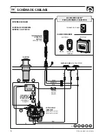
Page 12: ...SING CONTACTOR UNIT MOD T6415 12 12V MOD T6415 24 24V C A2 FOOT SWITCHES MOD 900U AND 900D BLACK BROWN BLUE BROWN BLACK BLUE FUSE 4A 12V 2A 24V L3 L2 L1 L4 L5 BASIC SYSTEM SEE PAGE 34 SHOWING THE MAIN...

Page 13: ...dle is inserted in the drum or into the gypsy cover WARNING Quick recommend using a circuit breaker designed for direct current DC with delayed action thermal magnetic or hydraulic magnetic to protect...

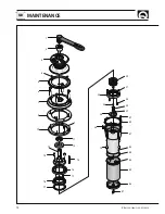
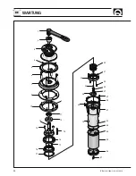
Page 14: ...14 GB TOTEM 600 1000 1100 REV005A 37 34 35 36 33 12 16 26 19 18 20 22 24 14 10 8 7 6 5 4 3 13 15 17 31 30 14 32 29 25 27 28 23 21 2 1 11 9 MAINTENANCE...

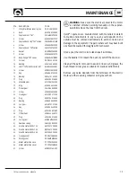
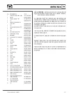
Page 15: ...2 Bush MSDFRAT00000 3 Capstan drum TM ZSGMSE10TM00 4 Screw MBV0410MXTSC 5 Capstan base ring TM series SGMBABW08TM0 6 Screw MBV0840MXCE0 7 Capstan base TM series SGMSC08TM000 8 Gasket PGBWTM080000 9 S...

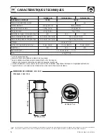
Page 16: ...up e Section minimale du c ble du moteur 3 Disjoncteur 4 Epaisseur du pont 5 Poids 1 A l arr t apr s utilisation 2 Measures prises en considerant le diam tre de la poup e 3 Valeur minimale conseill e...

Page 17: ...ctions conditions de garantie OUTILS NECESSAIRES POUR L INSTALLATION perceuse avec m ches 5 mm 13 64 9 mm 23 64 et 10 mm 13 32 gorge 108 mm 4 1 4 cl s hexagonale 10 mm et 13 mm ACCESSOIRES QUICK RECOM...

Page 18: ...LAIS INVERSEUR MOD T6415 12 12V MOD T6415 24 24V C A2 BOUTONS PIED MOD 900U ET 900D NOIRE MARRON BLEU MARRON NOIRE BLEU FUSIBLE 4A 12V 2A 24V L3 L2 L1 L4 L5 SYSTEME DE BASE SCH MA DE CONNEXION GENERAL...

Page 19: ...ec le levier introduit dans la poup e ou dans le couver cle du barbotin ATTENTION Quick conseille d utiliser un disjoncteur sp cifique pour courant continu DC et retard magn to thermique ou magn to hy...

Page 20: ...20 FR TOTEM 600 1000 1100 REV005A 37 34 35 36 33 12 16 26 19 18 20 22 24 14 10 8 7 6 5 4 3 13 15 17 31 30 14 32 29 25 27 28 23 21 2 1 11 9 ENTRETIEN...

Page 21: ...VSDN00000 2 Douille MSDFRAT00000 3 Poup e cabestan TM ZSGMSE10TM00 4 Vis MBV0410MXTSC 5 Anneau embase cabestan s ries TM SGMBABW08TM0 6 Vis MBV0840MXCE0 7 Embase cabestan s ries TM SGMSC08TM000 8 Join...

Page 22: ...rschnitt 4 Schutzschalter 5 St rke des Decks 6 Gewicht 1 Bei gekuppeltem Motor nach der Anlassphase 2 Messungen unter Ber cksichtigung des Seiltrommeldurchmessers durchgef hrt 4 Empfohlener Mindestwer...

Page 23: ...Scheibe 108 mm 4 1 4 Inbusschl ssel 10 mm und 13 mm EMPFOHLENE QUICK ZUBEH RTEILE Schalter an Bedientafel mod 800 Wasserdichte Fernbedienung mod HRC1002 Fu schalter mod 900 hydraulischer Schutzautoma...

Page 24: ...X MOD T6415 12 12V MOD T6415 24 24V C A2 FUSSSCHALTER MOD 900U UND 900D SCHWARZ BRAUN BLAU BRAUN SCHWARZ BLAU SICHERUNG 4A 12V 2A 24V L3 L2 L1 L4 L5 BASISSYSTEM ALLGEMEINER ANSCHLUSSPLAN S 34 L L1 L2...

Page 25: ...der Verholspill oder im Kettennuss deckel eingesetzt ist ACHTUNG Quick empfiehlt die Verwendung eines Spezialschalters f r Gleichstrom DC mit Verz gerung W rmeschutzschalter oder Hauptsicherungsautom...

Page 26: ...26 DE TOTEM 600 1000 1100 REV005A 37 34 35 36 33 12 16 26 19 18 20 22 24 14 10 8 7 6 5 4 3 13 15 17 31 30 14 32 29 25 27 28 23 21 2 1 11 9 WARTUNG...

Page 27: ...pplung MSDFRAT00000 3 Verholspill TM ZSGMSE10TM00 4 Schraub MBV0410MXTSC 5 Verholwinde Grundlagenring Serie TM SGMBABW08TM0 6 Schraub MBV0840MXCE0 7 Grundlage Verholwinde Serie TM SGMSC08TM000 8 Dicht...

Page 28: ...ci n m nima cables motor 3 Interruptor de protecci n 4 Espesor de cubierta 5 Peso 1 Despu s de un primer periodo de utilizaci n 2 Medidas efectuadas considerando el di metro de la campana 3 Valor m ni...

Page 29: ...AS NECESARIAS PARA LA INSTALACI N taladro con brocas 5 mm 13 64 9 mm 23 64 y 10 mm 13 32 de taza 108 mm 4 1 4 llaves hexagonales 10 mm y 13 mm ACCESORIOS ACONSEJADOS POR QUICK mando de panel mod 800 T...

Page 30: ...TELEINVERTIDORES MOD T6415 12 12V MOD T6415 24 24V C A2 MANDOS DE PIE MOD 900U Y 900D NEGRO MARR N AZUL MARRONE NERO BLU FUSIBLE 4A 12V 2A 24V L3 L2 L1 L4 L5 SISTEMA BASE DIAGRAMA DE CONEXI N GENERAL...

Page 31: ...inch con la palanca introducida en la campana o en la tapa del barbo ten ATENCI N Quick aconseja utilizar un interruptor espec fico para corrientes continuas DC y retrasado ma gneto t rmico o magneto...

Page 32: ...32 ES TOTEM 600 1000 1100 REV005A 37 34 35 36 33 12 16 26 19 18 20 22 24 14 10 8 7 6 5 4 3 13 15 17 31 30 14 32 29 25 27 28 23 21 2 1 11 9 MANTENIMIENTO...

Page 33: ...ara molinete recta nylon PVLVSDN00000 2 Br jula embrague 1000W R01 MSDFRAT00000 3 Campana winch TM ZSGMSE10TM00 4 Tornillo MBV0410MXTSC 5 Anillo base winch serie TM SGMBABW08TM0 6 Tornillo MBV0840MXCE...

Page 34: ...OL BOARD MOD 800 MOD 900 D DOWN FOOT SWITCH MOD 900 U UP L L1 L2 L3 L4 L5 MOTOR FUSE 4A 12V 2A 24V BATTERY HYDRAULIC MAGNETIC CIRCUIT BREAKER see table on page 4 10 16 22 28 C A2 A1 REVERSING CONTACTO...

Page 35: ...NOTE NOTES NOTES NOTIZEN NOTAS...

Page 36: ...15061 Fax 39 0544 415047 www quickitaly com E mail quick quickitaly com Codice e numero seriale del prodotto Product code and serial number Code et num ro de s rie du produit Code und Seriennummer des...

Reviews: