113
ENGLISH (113-501)
1
2
3
SELECTO
Control
Test run of loader and valve.
Attaching of implements
By releasing the oil pressure - push button "A/C" and
move lever in operating position - the connection of the
quick couplings will be easier.
NOTE ! turn off the engine, but keep the ignition on.
Function
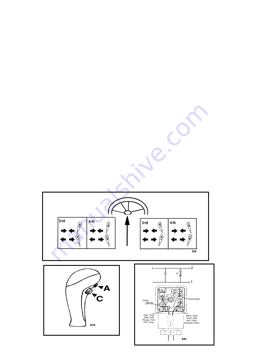
Fig 1, 2
Control lever in operating position for implement function
Push button (A) = Valve (3rd) in function
Push button (C) = Valve (4th) in function
Remark !
The equipment for the hydraulic locking of the imple-
ments shall be connected to the 4th valve function.
Trouble-shooting
If the valve doesn't work, check:
1. The current supply.
That the connector (fig.3) attached to the valve is
equipped with a light emitting diode (LED), which
gives light when the valve is operating.
2. That the voltage really is 12 V. Try with the tractor
engine turned on (the voltage of the battery may be
too low).
3. The connector, fig.3, is equipped with a diode (26 B)
to prevent sparking. Incrrect connection (see fig.E,
previous page) will destroy the diode. In such a case
the connectors (26) have to be exchanged. It won't
help just to correct the faulty connection.
The connector is available as spare part (5024376).
The damaged connectors shall be cut clean from the
cable. Connect the new ones (fig.3).
Summary of Contents for Q 900 Series
Page 171: ...125 125 501...


