background image

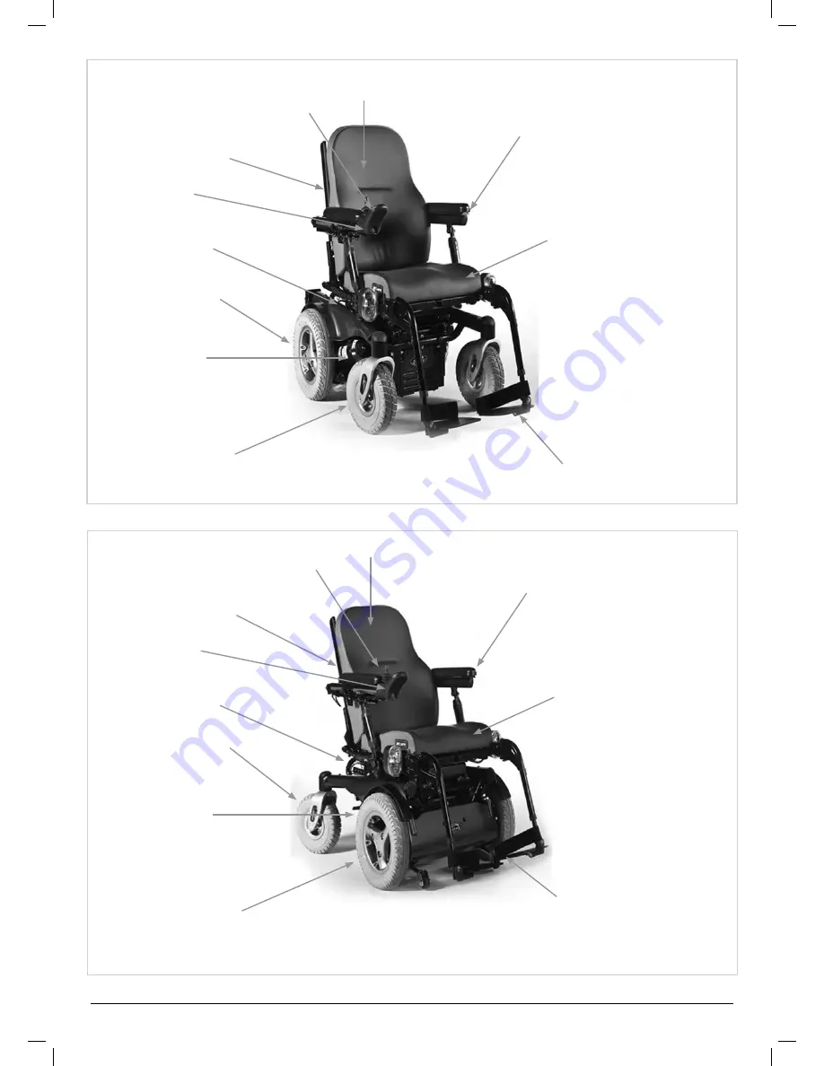
Quickie Jive     

5

back upholstery

heIght/wIdth

adjustable armrests

stabIlIsIng 

bar

battery box

drIve wheel

motors

foot rests

cushIon

hand control

module

joystIck

rear castors

back upholstery

heIght/wIdth

adjustable armrests

stabIlIsIng 

bar

battery box

drIve wheel

motors

foot rests

cushIon

hand control

module

joystIck

castors

Rear Wheel Drive (RWD)

Front Wheel Drive (FWD)

Summary of Contents for Jive

Page 1: ...Instructions for Use Quickie Jive Powered Wheelchair 000690669 00 ...

Page 2: ...om or alternatively is available on request in large text For further information on the full specification and options and accessories please refer to the order form All information is subject to change without notification Please consult Sunrise Medical with any queries you may have 1 5 m 1m R M F IPX4 IPX4 ...

Page 3: ...s and brain injuries Neurological disabilities e g MS Parkinson Illnesses such as heart and circulation deficiencies disturbance of equilibrium or cachexia as well as for elderly people who still have the strength in the upper body Persons who are mentally and physically able to control an input device to operate the chair and its functions in a safe way When considering provision please also note...

Page 4: ...ts the Quickie Jive is a perfect choice for easy service refurbishment and recycle requirements As a part of our ongoing product improvement initiative Sunrise Medical reserves the right to change specifications and design without notice Further not all features and options offered are compatible with all configurations of the wheelchair All dimensions are approximate and may be subject to change ...

Page 5: ...ttery Box Drive Wheel Motors foot rests cushion Hand control Module Joystick REAR Castors Back Upholstery Height width adjustable Armrests Stabilising Bar Battery Box Drive Wheel Motors foot rests cushion Hand control Module Joystick Castors Rear Wheel Drive RWD Front Wheel Drive FWD ...

Page 6: ...se button 27 7 8 Speed Profile increase button 27 7 9 Actuator button and LEDs 27 7 10 VR2 L 28 7 11 Charging and programming socket 29 7 12 VR2 dual control unit 29 7 13 Control button and indicator 29 7 14 Actuator button and LED 29 7 15 Maximum speed button and indicator 30 7 16 Quickie Direct Actuator Control Box 30 8 0 Troubleshooting The VR2 Hand Control 30 9 0 R net Control System 32 9 1 R ...

Page 7: ...Sunrise Medical want you to get the best out of your JIVE wheelchair This Owner s Manual will familiarise you with the chair and its features It contains hints on everyday usage and general care in addition to information on the high quality standards which we adhere to and details about the guarantee Your wheelchair should be delivered fully configured for your use there are a wide range of compo...

Page 8: ...urer s recommendations as stated in the Owner s Manual and or Service Manual Or failing to use only the specified original equipment parts b The wheelchair or part having been damaged by neglect accident or improper use c The wheelchair or part having been altered from the manufacturer s specifications or repairs having been attempted prior to the service agent being notified 2 4 Label explanation...

Page 9: ...stick WARNING Do not drive your wheelchair on a slope with the backrest reclined and or the seat lifted WARNING Maximum user weight for the chair will be either 240Kg 160Kg or 137Kg depending on the options Kerb climbing and model chosen WARNING Danger of finger entrapment WARNING When the seat is raised ensure the spring pin clicks back into the lock position to hold the seat upright 160Kg 137Kg ...

Page 10: ...ised restraint systems to keep the upright body position during decending or ascending ramps curbs or obstacles 4 4 Routine service The recommended service interval is one year See service history table in section 16 4 5 Emergency freewheel DANGER Please remember that you have no braking facility when the freewheel levers are moved from the normal drive position to the freewheel position Fig 4 1 A...

Page 11: ...en transporting your wheelchair Battery and charger type 24V 2x12V 73 Ah 20h Maintenance free Dimensions 260 x 171 x 210 mm 24V 2x12V 60 Ah 20h Maintenance free Dimensions 256 x 169 x 178 mm Connector 3 pins Neutrik type polarity scheme in section 17 4 10 Tyres Your wheelchair tyres can wear depending on use Check them regularly in accordance with the service instructions in this manual especially...

Page 12: ...ossible injury NOTE Extreme variances in temperature may trigger the self protect mechanism in the control system If this occurs the control system will temporarily shut down to prevent damage to the electronics or the chair 4 16 Ramps WARNING When using a ramp please ensure that it is capable of taking the combined weight of the power chair and yourself If a ramp is being used to load a chair int...

Page 13: ...own steep descents below the speed of 5kph and stop if any anxiety arises regarding directional control If the chair picks up speed centre the joystick to slow it or to stop all forward movement then restart slowly and do not allow the speed to increase NOTE The solid state controller has the benefit of a logic system that will help compensate when driving along a camber or up a hill This is an ad...

Page 14: ...ever use a forecourt pump Inspect all tyres regularly for signs of wear Do not drive over anything that could cause punctures in the tyres Ensure that there are no objects in your path that could possibly become lodged in your chair mechanism or in the spokes of the rear wheels This could cause the chair to come to a sudden stop Riding over drains or grids could cause the wheelchair castors or whe...

Page 15: ...heat sources on the tray as this could cause the tray to deform and mark Ensure that all extremities and clothing are free when positioning the tray for use 4 33 Using a kerb climber WARNING Always approach a kerb at 90 Fig 4 3 Approach the kerb step head on driving forwards slowly and steadily and always at a 90 angle RWD Chair As the kerb climber or castor makes contact with the kerb step the wh...

Page 16: ... fit every chair with the leg rests 4 33 3 Kerb climber fitting and removal procedure RWD base only Locate the kerb climber bar into the left hand location bracket and push it into the right hand receiver bracket Fig 4 4 and Fig 4 5 Hold the kerb climber with your right hand in the receiver bracket Align the holes of the receiver bracket and the kerb climber tube and plug in the locking pin from t...

Page 17: ...e of 10Nm Fig 4 15 Adjust the lap strap to suit leaving no more than a hand s width gap for comfort and safety The hand clearance should be with the lap strap under normal tension and not allow large gaps or loops Fig 4 16 Generally the lap strap should be fixed so that the straps sit at an angle of approximately 45 Fig 4 17 and when correctly adjusted should not allow user to slip down in the sea...

Page 18: ...e taken if the chair is in freewheel To remove the control pod VR2 Loosen the adjustment screw on the control arm and slide the arm out of the bracket Fig 5 3 Place the controller and arm in a safe place until required R net Locate the in line bus connector Gently pull the plugs apart to separate the loom Fig 5 4 To reconnect the hand control just repeat the process in reverse 5 3 Re Assembling Fl...

Page 19: ...sporting your wheelchair 5 7 Arm Rests 5 7 1 Arm Rests removing The arm rests on both sides of the wheel chair can be removed to allow side transfer Please refer to your appropriate arm rest type For single post arm rests Undo the finger wheel at the bottom of the post Fig 5 1 Lift the arm rest out of the receiver Fig 5 1 Reclining arm rest Undo the star wheel at the bottom pivot of the arm rest L...

Page 20: ... not to trap your fingers 5 8 1 Leg rest removal To swing away the leg rest Depress the retaining catch and swing the leg rest out Fig 5 13 Lift the leg rest up and off if removal is required Fig 5 14 To refit Line up the holes and studs Fig 5 15 Drop the leg rest into the receiver Push the leg rest inwards until it clicks shut Fig 5 16 To adjust the angle Fig 5 17 5 18 Use a 5 0mm Allen key and 1...

Page 21: ...2 Control The actuator buttons can operate any factory approved actuator Operation is dependent on what options are fitted to your wheelchair Fig 5 24 To operate the leg rests seat tilt seat lift or backrest recline Push one of the actuator buttons that has the seat icon on it to select actuator mode Operate the joystick left or right to select the actuator required actuator 1 or actuator 2 Select...

Page 22: ...rection to move the leg rest seat lift tilt or recline up or down Release the joystick when the desired angle is reached To return to drive mode press the actuator button again R net Control Please refer to your R net Owner s Manual for details 6 0 Seating 6 1 Seat cushions Seat cushions supplied by Sunrise Medical will have Velcro strips that correspond to patches on the seat WARNING You must ens...

Page 23: ...cushion 6 5 Backrest folding for transport Although there are a variety of back upholsteries which can be used on the Jive backrest structure they all fold down in the same way To fold the backrest Fig 6 7 Release the retainer pins on both sides Fold down the backrest at the junction with the seat frame Reverse the procedure to reinstate the backrest WARNING You must ensure the two retainer pins a...

Page 24: ...the red LED adjacent to the desired actuator button Operate the joystick in the forward or rearward direction to move the recline up or down Release the joystick when the desired angle is reached To return to drive mode press the actuator button again 6 7 Manual adjustable backrest manual recline For depth adjustment see section 6 2 To recline the backrest angle pull the lever at the top of the ba...

Page 25: ...ick in the forward or rearward direction to move the seat lift up or down Release the joystick when the desired height is reached To return to drive mode press the actuator button again CAUTION Once the seat is fully raised or fully down do not hold the joystick in its operating position as this could damage the actuator R net Control Please refer to your R net Owner s Manual for details 6 11 3 Po...

Page 26: ... unauthorised use The locking method is via a sequence of key presses and joystick movements as detailed below To lock the wheelchair While the control system is switched on depress and hold the On Off button After 1 second the control system will beep Now release the On Off button Deflect the joystick forwards until the control system beeps Deflect the joystick in reverse until the control system...

Page 27: ...dicates if the speed of the wheelchair is being limited or if the control system is locked 7 6 The horn button The horn will sound while this button is depressed 7 7 Speed Profile decrease button This button decreases the maximum speed setting or if the control system is programmed for drive profile operation selects a lower drive profile 7 8 Speed Profile increase button This button increases the...

Page 28: ...operate this button the associated LED will flash at the same rate The left and right turn indicator LEDs will also flash If the LED flashes rapidly either a total short circuit a single lamp open circuit or a total open circuit in the entire indicator circuit has been detected Depress the hazard warning button to turn off the lights and the associated LED Actuator button and LEDs Depending on whe...

Page 29: ...hich joystick has control If the red wheelchair light is on the wheelchair occupants joystick has control If the green attendant light is on the dual attendant systems joystick has control The button is used to transfer control between the two choices Fig 7 4 7 14 Actuator button and LED All VR2 dual attendant systems have an actuator button fitted as standard If the VR2 is programmed with no actu...

Page 30: ...ine Push the toggle switch for the relevant actuator forward until you reach the required angle height Release the toggle switch and the actuator will stop When the actuator reaches its maximum minimum position do not hold the toggle switch in its operating position as this could damage the actuator Fig 7 5 Fig 7 5 8 0 Troubleshooting The VR2 Hand Control Always consult your Sunrise Medical author...

Page 31: ...the battery If the connections are good try charging the batteries 2 The left hand motor has a bad connection Check the connections to the left hand motor 3 The left hand motor has a short circuit to a battery connection Contact your Sunrise Medical authorised dealer 4 The right hand motor has a bad connection Check the connections to the right hand motor 5 The right hand motor has a short circuit...

Page 32: ...lutions to many situations thereby enhancing the lifestyle and independence of the user The operation of the R net wheelchair control system is simple and easy to understand Both the R net and VR2 control systems incorporates state of the art electronics the result of many years of research to provide you with ease of use and a very high level of safety Because of the comprehensive nature of the R...

Page 33: ...warnings Fig 10 1 WARNING Before adjusting the swing away arm switch off the controller to avoid accidental displacement of the joystick which would cause unwanted movement of your wheelchair Be aware that the width of your chair has increased if the swing away arm is out and you may not get between certain obstacles Do not hang any items on or over the parallel swing away remote assembly as this ...

Page 34: ...ake sure that the controller is fixed securely to the centre bar Always turn off the power to the controller before moving the controller out of the way 10 5 Tray mount control R net WARNING The maximum weight allowed for the tray is 2 5kg Do not overload the tray this could cause the tray to break or could cause the chair to become unstable Always turn off the power to the controller before movin...

Page 35: ...endant and or the person sitting in the wheelchair please contact your Sunrise Service agent for adaptation If the direction of movement of the forus attendant control needs to be altered please contact your authorised Sunrise Medical dealer for adaptation 10 8 Powered swing away arm R net This option Fig 10 4 is used to mount all chin controls or the sip and puff and can be operated by either a b...

Page 36: ...he right and left headpieces are for right and left directional motion respectively The fourth switch is your mode switch and it toggles the head array between forward and reverse and between driving the wheelchair and operating any ancillary devices such as powered seating or augmentative communications systems Switching modes A variety of mode switches are available These can be divided into thr...

Page 37: ... which makes it suitable to use outdoors and when the joystick isn t used for long periods a hood can be placed over it Fig 11 7 This will give extra 11 6 Proportional chin control Fig 11 8 The proportional chin control must be used in conjunction with the Omni Plus module This is to give visual feedback for the selection of drive profiles and seating options WARNING Do not replace the joystick kn...

Page 38: ... seat power supply To replace them contact your Sunrise Medical authorised dealer who will also diagnose the fault 12 3 Common battery statements Over the years battery technology has moved forward but unfortunately some of the advice given on battery care has not This has resulted in a number of confused and at times contradictory instructions on the best way to care for your batteries This secti...

Page 39: ... free batteries take longer to fully charge than wet lead acid batteries 9 The battery terminals need to be checked regularly for signs of corrosion If any corrosion is apparent then clean the terminals completely and re grease the terminal using Vaseline petroleum jelly not ordinary grease Ensure that the terminal nut and bolt cable clip and exposed cable are completely covered with jelly 10 Foll...

Page 40: ...nsion cord should not be used unless absolutely necessary Use of an improper extension cord could result in a risk of fire and electric shock If any extension cord must be used make sure the pins on the plug of the extension cord are the same number size and shape as those of the plug on the charger and that the extension cord is properly wired and in good electrical condition WARNING Always switc...

Page 41: ...ery warranties are subject to periods set by the manufacturers However most of these warranties are subject to a wear and tear clause and if you genuinely wear out your batteries in 6 months it will not be possible to obtain a replacement under warranty WARNINGS Make sure the cord is located so that it will not be stepped on tripped over or otherwise subjected to damage or stress Do not rest a bat...

Page 42: ...the equivalent level of safety and security as a vehicle seating system Sunrise Medical recommends that the user transfers to the vehicle seating and uses the vehicle installed restraint system wherever possible Sunrise Medical recognises that it is not always practical for the user to be transferred and in these circumstances where the user must be transported whilst in the wheelchair the followi...

Page 43: ...s should be attached as close as possible at an angle of 45 degrees and tightened securely in accordance with the manufacturer s instructions Alterations or substitutions must not be made to the wheelchair tie down points or to structural and frame or components without consulting the manufacturer Failure to do so will invalidate the ability of a Sunrise Medical wheelchair to be transported within...

Page 44: ...belts must be adjusted as tightly as possible consistent with user comfort Restraint belt webbing must not be twisted when in use Restraints should be mounted to the vehicle B pillar and should not be held away from the body by wheelchair components such as armrest or wheels Fig 13 4 The tie down symbol Fig 13 6 on the wheelchair frame indicates the position of the wheelchair restraint straps The ...

Page 45: ...5 FWD Front Tie Down FWD Rear Tie Down FWD Front and Rear Tie Down Straps Fig 13 10 MWD Front Tie Down MWD Rear Tie Down MWD Front and Rear Tie Down Straps Fig 13 12 Fig 13 13 Fig 13 14 Fig 13 15 Fig 13 11 TIE DOWNS ...

Page 46: ...ding and unloading Take this Owner s Manual with you and if fitted take the R net Owner s Manual also The carrier will need to refer to the following sections How to lock unlock the Joystick Section 7 3 Section 4 32 R Net Owners Manual How to disconnect the batteries Section 12 1 How to disconnect the drive Section 5 4 13 6 Medium to long term storage When storing your wheelchair for long periods ...

Page 47: ... remove the wheel tyre Please see below and next page for photographs Use a 8 0 mm hex key to loosen the 3 Socket studs Fig 14 2 Jack the wheel up and support it using blocks Fig 14 3 Remove the 3 studs and pull the wheel away from the hub Remove the valve cap and let the air out of the tyre by gently pressing the valve stem with a small screw driver Fig 14 4 There are 6 rim studs that must be loo...

Page 48: ...48 Quickie Jive Fig 14 8 Fig 14 6 Fig 14 7 Fig 14 4 Fig 14 5 1 2 3 5 4 6 Fig 14 9 Fig 14 3 Fig 14 10 Valve Gap ...

Page 49: ...ner socket to undo the axle bolt Fig 14 11 Remove the nyloc nut Fig 14 12 Refitting When refitting do not try to force the bolt through Gently move the wheel back and forth until the bolt slips through WARNING Always use a new nyloc nut when refitting Fig 14 11 Fig 14 12 ...

Page 50: ...ion Use a 5 0mm hex key remove the 2 axle studs Fig 14 13 Remove the centre spacers and spindle Fig 14 14 For pneumatic tyres let the air out of the tyre Undo the 3 hub studs Fig 14 15 Lift the hubs out Fig 14 16 Gently feed the tube out of the tyre Fig 14 17 When refitting the hub studs tighten to a torque of 15 20Nm Fig 14 13 Fig 14 14 Fig 14 16 Fig 14 17 Fig 14 15 ...

Page 51: ...or clothes dyes should be removed immediately to prevent long term staining CAUTION Do not use solvents bleaches abrasives synthetic detergents wax polishes or aerosols Disinfectants may be used in dilution as specified by their manufacturer Ensure surfaces are rinsed with clean water and dried thoroughly Cleaning instructions for all and Recaro CAUTION You should remove stains on your seat as soo...

Page 52: ...ase proceed in the following way Front and Rear Lights Bulb Refer to Fig 14 18 14 20 Use a flat bladed screwdriver to gently lever off the plastic cover Lift the cover away carefully Use a cross blade jewellers screwdriver to undo the small lamp cover screw Carefully lift the lamp cover off Take care not to loose the screw The lamp is a 5W 12v 90 bayonet fit The lamp lamp cover and screw Front and...

Page 53: ...ng parts and the rubber covers fit fully over the battery terminals NOTE After connection of the batteries wait 2 minutes for the system to reset before switching on the control system This reset time is required every time the batteries are disconnected Connecting Disconnecting the Batteries Undo the two seat interface screws Section 12 1 Flip the seat frame backwards until the automatic lock pin...

Page 54: ...ing cloth and dilute disinfectant Wire brush Petroleum jelly WARNING If in any doubt about performing any maintenance on your wheelchair contact your Sunrise Medical authorised dealer Daily checks With the control system switched off check that the joystick is not bent or damaged and that it returns to the centre when you push and release it Visually inspect the wheelchair to make sure the legrest...

Page 55: ...ir contact your Sunrise Medical authorised dealer After performing any maintenance or repairs on the wheelchair you must make sure that it is functioning correctly before it is used A complete inspection safety check and service should be made by a Sunrise Medical authorised dealer at least once per year Maintenance and Inspection Schedule Daily Weekly Quarterly Six month Annually Check battery le...

Page 56: ...at height Not with Balle unit Static stability sideways 0 19 2 0º tilt 0º recline max seat height Energy consumption Max Range 35km Depending on terrain speed and user weight Dynamic stability uphill 10 Obstacle climbing 100 mm 100 kg 75 mm at 160 kg Maximum speed forward 6 km h 13 km h Minimum braking distance from max speed 3 1m Dependant on programming Seat plane angle 0 9 Not with Balle Tilt f...

Page 57: ...line max seat height Energy consumption Max Range 35km Depending on terrain speed and user weight Dynamic stability uphill 6 Obstacle climbing 75mm 100 mm 100 kg 75 mm at 160 kg Maximum speed forward 6 km h 10 km h Minimum braking distance from max speed 3 1m Dependant on programming Seat plane angle 0 9 Not with Balle Tilt fitted Effective seat depth 400 mm 560mm Effective seat width 400 mm 560 m...

Page 58: ... km Depending on terrain speed and user weight Dynamic stability uphill 10 Obstacle climbing 100 mm 100 kg 75 mm at 160 kg Maximum speed forward 6 km h 13 km h Minimum braking distance from max speed 3 1m Dependant on programming Seat plane angle 0 9 Not with Balle Tilt fitted Effective seat depth 400 mm 560mm Effective seat width 400 mm 560 mm Seat surface height at front edge 430 mm 480 mm With ...

Page 59: ... accordance with local laws and regulations your product should be disposed of separately from household waste When this product reaches the end of its life take it to the local collection point designated by local authorities The separate collection and recycling of your product at the time of disposal will help conserve natural resources and ensure that it is recycled in a manner that protects t...

Page 60: ... 0523 573111 Fax 0039 0523 570060 e mail info sunrisemedical it website www SunriseMedical com Sunrise Medical AG Lückhalde 14 3074 Muri Bern Schweiz Suisse Svizzera Fon 41 0 31 958 3838 Fax 41 0 31 958 3848 www SunriseMedical com Sunrise Medical AS Dynamitveien 14 b 1400 Ski Norway Tel 47 0 66963800 Faks 47 0 66963880 www SunriseMedical no Sunrise Medical AB Box 9232 400 95 Göteborg Sweden Tel 46...

Reviews: