108833 Rev. C
26
S - 6 3 6 / S - 6 4 6
X. OPERATING INSTRUCTIONS
G. RNET CONTROLLER
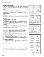
The Rnet control system has two versions of the Joystick Module – with and without lighting con-
trol. Most of the controls are common to both; however, the lighting buttons are only included on
the Joystick Module with lighting control. Each of the controls is explained within this section.
Joystick
The primary function of the joystick is to control the speed and direction of the wheelchair.
The further you push the joystick from the center position the faster the wheelchair will
move. When you release the joystick the brakes are automatically applied. If the wheelchair is
fitted with actuators, the joystick can also be used to move and select actuators, refer to sec-
tion 5.5 for more details.
On/Off Button
The On/Off button applies power to the control system electronics, which in turn supply power
to the wheelchair’s motors. Do not use the On/Off button to stop the wheelchair unless there is
an emergency. (If you do, you may shorten the life of the wheelchair drive components).
Horn Button
The Horn will sound while this button is pressed.
Mode Button
The Mode button allows the user to navigate through the available operating Modes for the
control system. The available modes are dependent on programming and the range of auxil-
iary output devices connected to the control system.
Profile Button
The Profile button allows the user to navigate through the available Profiles for the control
system. The number of available Profiles is dependent on how the control system is pro-
grammed. Depending on the way the control system has been programmed a momentary
screen may be displayed when the button is pressed.
Hazard Warning Button and LED
This button activates and de-activates the wheelchair’s hazard lights. Depress the button to
turn the hazards on and depress the button again to turn them off. When activated the haz-
ard LED and the indicator LEDs will flash in sync with the wheelchair’s indicators.
Lights Button and LED
This button activates and de-activates the wheelchair’s lights. Depress the button to turn the lights
on and depress the button again to turn them off. When activated the lights LED will illuminate.
Left Indicator Button and LED
This button activates and de-activates the wheelchair’s left indicator. Depress the button to
turn the indicator on and depress the button again to turn it off. When activated the left indi-
cator LED will flash in sync with the wheelchair’s indicator(s).
Right Indicator Button and LED
This button activates and de-activates the wheelchair’s right indicator. Depress the button to
turn the indicator on and depress the button again to turn it off. When activated the right
indicator LED will flash in sync with the wheelchair’s indicator(s).
External On/Off Switch Jack
This allows the user to turn the control system on and off using an external device, such as a
buddy button.
External Stereo Switch Jack (Assignable)
This allows the user to select programmed assigned functions using an external device, such as a
buddy button or toggle switch. If the control system is set to latched drive or actuator control
operation, then the polarity of the jack input is reversed to effect a fail safe system; meaning this
input will provide an External Profile Switch function and an Emergency Stop Switch function.
NOTE–
The Joystick Module is supplied with rubber bungs that must be inserted into the Jack Socket when
no external device is connected.
LCD Screen
The status of the control system can be understood by observing the LCD screen. The con-
trol system is on when the screen is backlit.
Charger Socket
Joystick
Communication Cable
Rnet Joystick Module
External On/Off Switch Jack
Horn Button
Profile Button
Lights Button
& LED
Left Indicator
Button & LED
Right Indicator
Button & LED
LCD Screen
LCD Screen
With Lighting
Without Lighting
Control Panels
Buttons
Jack Sockets
External Profile Switch Jack
On/Off Button
Mode Button
Hazard
Warning Button
& LED


