background image

8

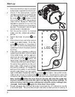
Start up 

LED


2   
3   
4   


LED

1.  Disconnect the NA contacts or detach 

temperature regulator from the boiler.

2.  Check  if  the  appropriate  system 

installation pressure is reached (see 

the  „TECHNICAL  DATA”  section). 

By  using 

  or 

  buttons  whilst 

the control panel is off, the pressure 

value  will  be  displayed.  When  the 

installation pressure is too low The 

„A’’ indicator flickers (see „Operating’’ 

section). This doesn’t concern open 

vented system installations.

3.  Set  the  pump  control  to  manual 

mode, see the „Advanced settings” 

section.

4.  Switch the boiler on (press 

 but-

ton).

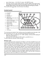
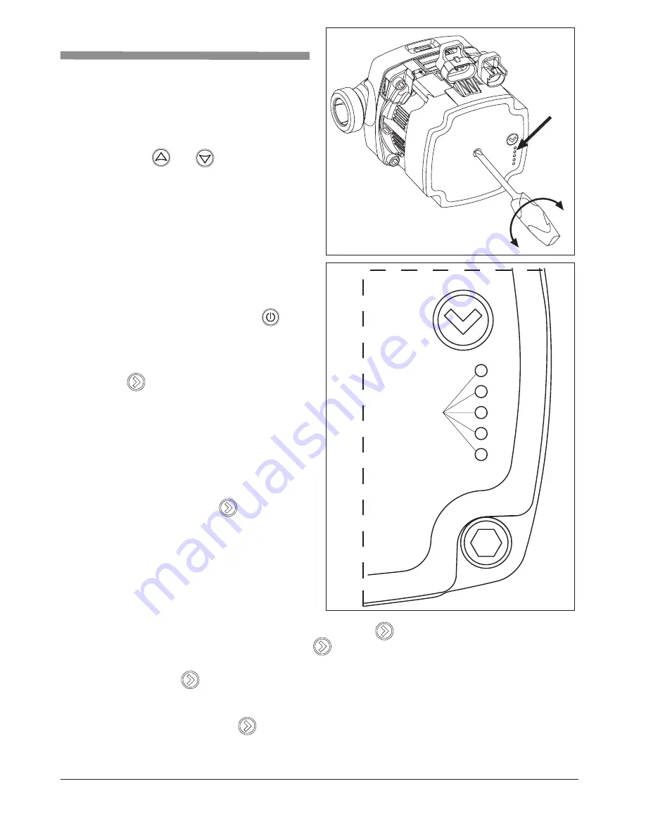
5.  Check the pump is set to the correct 

mode (see table below). To do this, 

press   button for no more than 2 

seconds. The LED’s should signal an 

operating mode at the place pointed 

by arrow.

6.  If the LEDs are signaling a different 

operating mode than recommended 

in the table below, set the appropri-

ate mode according to the following 

instructions:  press 

  button  for 

longer than 2 seconds, but less than 

10 seconds (LED’s will start to flash), 

the pump then switches to the set-

tings mode. LEDs glows to indicate 

the current settings. To change the 

settings of the pump in accordance 

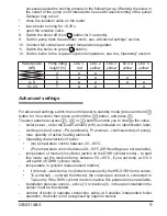
with the table below, you can set the 

right combination of glowing LEDs by pressing 


the button. Once LED combi-

nation is set correct, by not pressing 


the button for 10 seconds the pump will 

remember this setting and will exit from setting mode back to performance view.


Note: holding


 button for more than 10 seconds will enter the pump into 

key lock mode. this prevents the user from altering the pump settings. To 

remove the key lock the pump settings and allow the pump settings to be 

changed,  hold button


 again for more than 10 seconds.

7.  Ensure adequate flow through the boiler is reached (the „H” indicator is on with 

a constant light). The pump should self vent after a short period of running. if 

Summary of Contents for EKCO.LN2

Page 1: ...ELECTRIC CENTRAL HEATING FLOW BOILER QuickTec GmbH Bardelebenweg 25 14089 Berlin Germany Tel 49 0 30 577 01 88 40 Fax 49 0 30 577 01 88 49 E Mail mail quick tec com quick tec com...

Page 2: ...for recycling Appropriate utilisation of used product prevents potential negative environmental influences that may occur as a result of inappropriate handling of waste In order to get more detailed...

Page 3: ...l is equipped with a differential pressure relief valve bypass It allows the system to keep minimal flow of heating medium through the boiler and reduce noises in installation during the thermostatic...

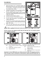
Page 4: ...entry 8 Once you have finished the above procedures you can start the boiler See the Start up section While applying thermostat make sure there is no voltage on its entry Do not connect any voltage i...

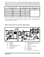
Page 5: ...xtra expansion vessel should be installed on it Temperature of heating medium feed and return Capacity of central heating system Pressure in central heating system C l bar 85 70 58 1 5 70 55 79 55 45...

Page 6: ...not run close to mains cables they must not go around other electric wires Important To activate the sensor and DHW cylinder heating please follow the in structions in section ADVANCED SETTINGS Set up...

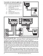
Page 7: ...try so that when a master appliance gets on the contact will be opened the boiler switched off When the NA contact gets opened heating will get off and the pump stopped The EKCO LN2 and EKCO L2 model...

Page 8: ...n the table below set the appropri ate mode according to the following instructions press button for longer than 2 seconds but less than 10 seconds LED s will start to flash the pump then switches to...

Page 9: ...external external thermostat the close open contact is connected to Tzas entry If the DHW cylinder mode is inactive this parameter is unavailable installation pressure sensor active 1 or inactive 0 i...

Page 10: ...nt Do not cut power supply off between heating season When the control panel is switched to Stand by mode the control panel is off the F icons flickers only In this mode the boiler is off but the pump...

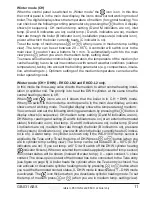
Page 11: ...ing system is off When and icons are on it shows that the boiler is in C H DHW mode When you switch to this mode the control panel is in the main view display an icons show current working mode The di...

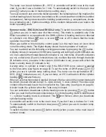
Page 12: ...r is on inlet temp D and K indicators are on outlet temp D and L indicators are on medium flow rate through the boiler B indicator is on pressure in the system A indicator is on power with which the b...

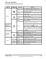
Page 13: ...CO L2 boiler heats the DHW icon is on all models temp in CH system is lower than required but the required room temperature has been reached RP entry is open or room thermostat is blocked EKCO LN2 EKC...

Page 14: ...act an authorised service or the seller G indicator is off in winter mode a failure of installation that con nect a room thermostat contact an authorised service or the seller a failure of electronic...

Page 15: ...0 27 0 17 0 15 0 27 Rated power kW 12 15 18 21 24 Rated voltage 400V 3N Rated current A 3x17 3 3x21 7 3x26 0 3x30 3 3x34 6 Fuse rated current A 20 25 32 40 Min connecting wires section mm2 5 x 2 5 5...

Page 16: ...QuickTec GmbH Bardelebenweg 25 14089 Berlin Germany Tel 49 0 30 577 01 88 40 Fax 49 0 30 577 01 88 49 E Mail mail quick tec com quick tec com...

Reviews: