READ AND SAVE THESE INSTRUCTIONS
WARNING
TO REDUCE THE RISK OF FIRE, ELECTRIC SHOCK, OR INJURY
TO PERSONS, OBSERVE THE FOLLOWING:
1. Use this unit only in the manner intended by the manufacturer. If
you have questions, contact the manufacturer at the address or
telephone number listed in the warranty.
2. Before servicing or cleaning unit, switch power at service panel
and lock the service disconnecting means to prevent power from
being switched on accidentally. When the service disconnecting
means cannot be locked, securely fasten a prominent warning
device, such as a tag, to the service panel.
3. Installation work and electrical wiring must be done by a
d
person(s) in accordance with all applicable codes and standards,
.
4.
air is needed for proper combustion and exhausting of
gases through the
(chimney) of fuel burning equipment to
prevent backdrafting. Follow the heating equipment manufacturer's
guidelines and safety standards such as those published by the
National Fire Protection Association (NFPA), and the American
Society for Heating, Refrigeration and Air Conditioning Engineers
(ASHRAE), and the local code authorities.
5. The wiring must be permanent. DO NOT USE AN EXTENSION
CORD! Use 14 GA. MINIMUM copper wire. Although the Powered
Attic Ventilator may be wired directly to power, we advise that
some type of shut switch be installed in the line. Please see the
section on electrical wiring for suggested wiring diagrams and
instructions.
6. This unit must be grounded.
2. Fan may equipped with a thermostat which may start
fan
automatically. To reduce risk of injury or electric shock while
servicing and cleaning unit, switch power at service panel and
lock service panel to prevent power from being switched on
accidentally.
3.
QC Manufacturing, Inc. recommends two-three
square feet of
open air inlet per fan.
Vents for attic side wall installations should
be added or installed at opposite end.
4. This ventilator is intended for Gable installation.
Screwdriver (Phillips)
Tape Measure
Pencil
Electrical Supplies (to comply with codes)
TOOLS & MATERIALS REQUIRED
PREPARE THE VENTILATOR
1.
:
x
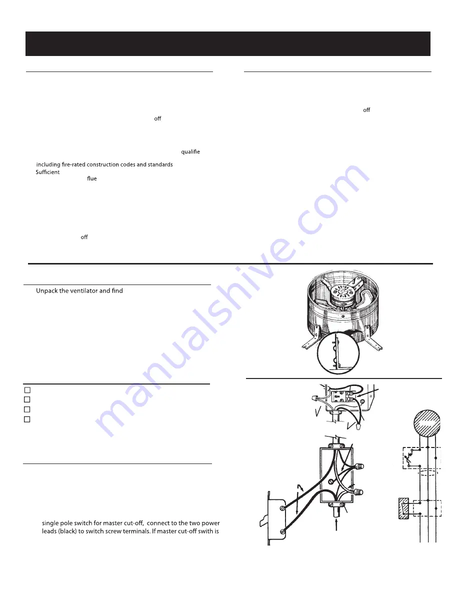
4 - angle brackets
12- sheet metal screws
2. Fasten the four (4) angle mounting brackets to the housing
using the twelve (12) sheet metal screws provided.
1. For general ventilating use only. Do not use to exhaust hazardous
or explosive materials or vapors.
CAUTION
ATTIC FAN - Gable
(Power Attic Ventilator)
WIRE THE VENTILATOR
1. Remove the Junction box cover plate. Bring the power
cable at least 6” into the Junction box. Fasten to box
with appropriate connector.
2. For standard installation, connect the two leads from the ther-
mostat wiring box to the two power leads (black). Attach ground wire
from the power cable to the green screw in the box. If using
located in another location then connect the two power leads (black)
to each other with wirenut and screw cover back on box.
TO
MOTOR
GROUND TO
SWITCH
BOX
WHITE
BLACK
THERMOSTAT
WHITE
MASTER
ON-OFF SWITCH
120 VOLTS
LINE IN
MOTOR
VENTILATOR
WIRING BOX
MASTER
ON-OFF
SWITCH
BLK
GRD
WHT
BLACK
BLK
GRD
WHT
BLACK
GROUND TO
SWITCH BOX
WHITE


