background image

QUIETCOOLSYSTEMS.COM

5

WELCOME

INST

ALLA

TION

WIRING

OPERA

TION

W

ARRANTY

Installation Video:

Watch the video by scanning the QR 

code or visit


www.QuietCoolSystems.com/support

2.   INSTALLATION

2.1   INSTALLING THE GA ES-1500


VERY IMPORTANT:

 MINIMUM OF 26” CLEARANCE REQUIRED


ABOVE CEILING FOR INSTALLATION OF GA MODEL FANS.


ALWAYS FOLLOW LOCAL BUILDING CODES.


1.  Determine in which area you would like to install your QuietCool


Garage Attic Fan. 

2.  Now it’s time to find the exact location using a stud finder or by


going up into the attic and finding the location. Locate the ceiling   


studs and mark the location for the fan to be installed. 

3.  One side of the cut out should be directly next to a wood member


for proper fan mounting and support. 

 NOTE: 

The QuietCool Damper Box includes removable flanges 


in the case that you are installing the damper box between


studs that are exactly 16” on center. To remove the flanges, 


simply take a screwdriver and pry between the flange surface 


and the damper box. Do this along the entire edge of the flange 


and it will pop off.

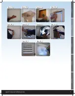
4.  When you find the location, from down below mark a square using  


the template. Make sure you have 2” of clearance all the way around  


it so the grille fits with no obstructions. 

(see Figure  2.1A)

5.  Starting at one corner of the square using a drywall saw, cut out


the opening. Remove the drywall cutout and clear away insulation (if  


applicable). 

(see Figure 2.1B)

6.  Take the GA fan model into the attic and place it over the ceiling cut  

 out. 

(see Figure 2.1C). 

If needed, you can remove the ceiling flanges 


and pass the fan directly through the ceiling cut-out.


7.  Attach the fan using screws into the ceiling joists. 

(see Figure 2.1D)


8.  Install the ceiling grille. 

(see Figure 2.1E)


VERY IMPORTANT:

 Check to make sure fan blade spins freely   


  and the fire damper closes easily. Make sure to secure the clip  


  in the open position.

!

!

!!

Figure 2.1A

Figure 2.1B

Figure 2.1C

Figure 2.1D

Figure 2.1E

!

!

Summary of Contents for GA ES-1500

Page 1: ...DO NOT THROW AWAY SERIAL NUMBER FOR FAN IS LOCATED ON THE BACK COVER OF THE OWNER S GUIDE LEAVE WITH HOMEOWNER OWNER S GUIDE GARAGE FANS GA ES 1500 GX ES 1100...

Page 2: ...ing the Wall Switch 12 4 2 Frequently Asked Questions 13 WARRANTY 15 QC MANUFACTURING INC 26040 YNEZ ROAD TEMECULA CA 92591 PHONE 1 888 QUIETCOOL WEBSITE WWW QUIETCOOLSYSTEMS COM WARNINGS CAUTION This...

Page 3: ...e or workshop We offer the GA ES 1500 Garage Whole House Fan to ventilate both your garage and attic We also offer the GX ES 1100 to ventilate your garage only with a wall mount design 1 2 FEATURES Ul...

Page 4: ...or effectively as it could with 1 750 attic venting But don t worry the system will still operate if there is not enough venting Insufficient venting is a very simple problem to fix Roofing contractor...

Page 5: ...t are exactly 16 on center To remove the flanges simply take a screwdriver and pry between the flange surface and the damper box Do this along the entire edge of the flange and it will pop off 4 When...

Page 6: ...e 5 From the interior drill a hole through the exterior at the four corners of the cut out see Figure 2 2C 6 Go to the exterior and place the square wall mounting bracket aligned to the 4 drilled hole...

Page 7: ...QUIETCOOLSYSTEMS COM 7 WELCOME INSTALLATION WIRING OPERATION WARRANTY Figure 2 2A Figure 2 2B Figure 2 2C Figure 2 2D Figure 2 2H Figure 2 2G Figure 2 2F Figure 2 2E Figure 2 2J Figure 2 2I...

Page 8: ...thermostat readings which is usually on the wall next to the light switch or garage door opener in the garage Begin wiring the thermostat 2 With a 3 wire Romex tie the black wire to the black wire fr...

Page 9: ...ource to the ground screw in the Hub 7 Set the dip switch positions inside the Hub as shown in the diagram Power Cord Attach green ground wires to ground screw All White Common Wires Together POWER TI...

Page 10: ...e Test LED indicator will light up as shown below when the Test button is pressed and when the fan is turned on via the Wall Switch High Speed LED indicator will blink three times every two seconds PA...

Page 11: ...ators will be blinking indicating successful pairing Press the Wall Switch button again the speed indicators will go out and it will display the current fan status Press the Timer button to test the W...

Page 12: ...the plate onto the drywall through the four mounting holes 1 2 4 8 12 H M L 1 2 4 8 12 H M L 4 SYSTEM OPERATING INSTRUCTIONS 4 1 OPERATING THE WALL SWITCH TIMER BUTTON The top button on the switch con...

Page 13: ...In order for the fan to run a Timer selection MUST be made When the Timer status is off no LED indicators lit you can still change the Speed setting The Speed setting will take effect once the Timer...

Page 14: ...is an indication that your DIP switches are not in the correct position Disconnect power adjust your DIP switches and the only light that should be lit is your RED power light HOW DO I CHANGE THE DIP...

Page 15: ...of our equipment or any malfunction thereof 2 Cost of service calls to diagnose the cause of problems or the labor charge to un install any components 3 Product failure or damage due to faulty instal...

Page 16: ...FAN SERIAL NUMBER INFORMATION RETAIN FOR YOUR RECORDS SERIAL NUMBER IS REQUIRED FOR WARRANTY PURPOSES 1 888 QUIETCOOL WWW QUIETCOOLSYSTEMS COM Rev 10 5 20...

Reviews: