background image

1-888-QUIETCOOL 

10

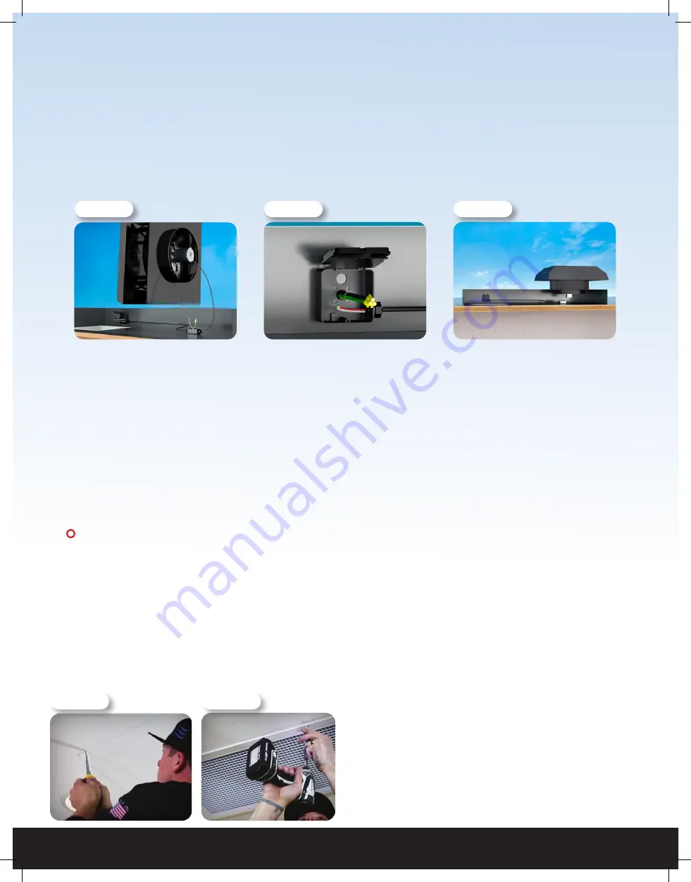
1.  Once you have determined the location for both the fan and damper grille, use the supplied square 

template to cut out your roofing and ceiling material for the supplied Plenum Flash Mount and  

damper grille. 

2.  Secure the Flash Mount to the roof. Finish caulking around the Flash Mount and flash it into the roof to 

make a nice seal. Take the plenum box and slide the Flash Mount lip into the plenum box.


3.  Make sure the plenum box sits flush to the roof. Using roofing nails, fasten the plenum box to the roof 

using the six tabs located around the plenum box.

4.  Position the fan on it’s side allowing the RF Control Hub to hang in the circle fan hole in the plenum box. 

Remove the power cord and RF Control Hub from the fan flex. Run the fan flex into the junction box on 

the bottom floor of the plenum box. Remove junction box plate cover and tie wires together. Re-install the 

plate cover.

5.  Lifting the fan unit up at an angle, apply weatherproof caulking to the bottom side of the fan unit. This will 

help keep the fan in place and will seal nice and tight.

6.  Position the fan over the circle fan hole in the plenum box. Using the supplied self-tapping screws with 

rubber-bonded washers, attach the fan unit to the plenum box. Be sure to caulk around the screw head.

 IMPORTANT:

 If you have drywall on your ceiling, use the supplied template to cut out your grille hole. 

If you have open ceiling rafters with no drywall, you will need to frame in the grille. (See Figure 2.5D)

7.  Run your electrical piping or seal tight flex into the half inch knockout in the plenum box. From inside the 

home, mount the RF Control Hub into the half inch knockout in the plenum box. Bring your electrical wires 

into the backside of the RF Control Hub 

(See Figure 2.5B)

. Slide your lock nut over the wires and thread it 

onto the 1/2” flex connector to secure the RF Control Hub to the plenum box. Bring the fan wires from the 

harness inside the plenum box into the RF Control Hub 

(See Figure 2.5C).


8.  Follow the wiring instructions on page 11 to wire your RF Control Hub to the power source.


9.  Remove the damper grille and screws from its  


     packaging. Place the grille in the cutout. Install     

             the grille with the white screws provided. 

(See     

                Figure 2.5E)

!

!

NOTE:

 Wiring Diagrams are for examples ONLY. Wiring should be done by an  

experienced electrician.

NOTE: 

Your fan came with the RF Hub pre-wired to a power cord for testing purposes before 

installation. The power cord can be used when installed inside of an attic. DO NOT USE THE 

POWER CORD OUTDOORS. If you would like to hard-wire the fan, or it is required by your local 

building codes, please follow the wiring instructions below.

Figure 2.5D

Figure 2.5E

Figure 2.5A

Figure 2.5B

Figure 2.5C

Summary of Contents for RM WHF-4.0

Page 1: ...DO NOT THROW AWAY SERIAL NUMBER FOR FAN IS LOCATED ON THE BACK COVER OF THE OWNER S GUIDE LEAVE WITH HOMEOWNER OWNER S GUIDE ROOF MOUNT WHOLE HOUSE FAN RM WHF 4 0...

Page 2: ...9 3 WIRING 11 3 1 RM Whole House Fan Wiring 11 3 2 Fan Hub LED Indicators 12 3 3 Pairing the Wall Switch 13 3 4 Finding a Location forthe Wall Switch 13 3 5 Installing the Wall Switch 14 4 SYSTEM OPE...

Page 3: ...homes with a flat roof or homes with a sealed attic 1 2 FEATURES Ultra Energy Efficient Electronically Commutated Motor ECM Patent Pending Built in USA 15 Year Warranty Included RF Wireless Control K...

Page 4: ...empt to service the product 8 SAFETY PRECAUTIONS Do not install the fan in wet or windy conditions Tie off both yourself and your equipment when working on steep pitched roofs to avoid falls Wear safe...

Page 5: ...ist spacing is required for each installation type IMPORTANT If you are installing the RM WHF 4 0 PL skip to section 2 5 on pg 9 IMPORTANT Before installing the RM WHF 4 0 DB you will need to find the...

Page 6: ...sition Using a roofing knife cut a 4 inch horizontal slit in the shingles at the 9 o clock and 3 o clock positions of the hole allowing the fan s flashing to slide underneath the shingles 6 Apply weat...

Page 7: ...making sure that you have at least 2 inches of clearance all around it While holding the template in place mark its outline with a pencil See Figure 2 2C 6 Using a drywall saw or similar device cut o...

Page 8: ...ady to put your grille core back in place simply push it right into place and it will snap in tight 2 3 INSTALLING THE RM WHF 4 0 DG1 Use the following instructions to finish the installation of your...

Page 9: ...tion for your damper grilles Make sure the fan is equally centered between the two damper grille locations Make sure the damper grilles are installed in the same joist bay as the fan 2 When you have c...

Page 10: ...and will seal nice and tight 6 Position the fan over the circle fan hole in the plenum box Using the supplied self tapping screws with rubber bonded washers attach the fan unit to the plenum box Be s...

Page 11: ...ack wire from the power source to the black wire from the Hub 2 Connect the white wire from the power source and the white wire on the fan to the white wire from the Hub 3 Connect the red wire from th...

Page 12: ...AIR INDICATOR The Pair LED indicator will light up when making pair operations Please see below for details on pairing NOTES ON OPERATION If the Dip Switch is not configured correctly all the indicato...

Page 13: ...ators will be blinking indicating successful pairing Press the Wall Switch button again the speed indicators will go out and it will display the current fan status Press the Timer button to test the W...

Page 14: ...the plate onto the drywall through the four mounting holes 1 2 4 8 12 H M L 1 2 4 8 12 H M L 4 SYSTEM OPERATING INSTRUCTIONS 4 1 OPERATING THE WALL SWITCH TIMER BUTTON The top button on the switch con...

Page 15: ...In order for the fan to run a Timer selection MUST be made When the Timer status is off no LED indicators lit you can still change the Speed setting The Speed setting will take effect once the Timer...

Page 16: ...t power make your adjustment inside the hub and then reconnect power CAN YOU CONNECT THE RF CONTROL TO A SMART HOME SYSTEM LIKE ALEXA GOOGLE HOME OR APPLE HOMEKIT No in the current configuration the R...

Page 17: ...r home to prepare for bedtime Then when it s time for bed you should close all the windows in your main living space but leave the windows in your occupied bedrooms open This will provide each room wi...

Page 18: ...program is unlimited This means you can refer as many people as you like Best of all both you and your friend will earn 25 for each whole house fan that your friend installs QuietCoolSystems com refer...

Page 19: ...pment or any malfunction thereof 2 Cost of service calls to diagnose the cause of problems or the labor charge to un install any components 3 Product failure or damage due to faulty installation abuse...

Page 20: ...FAN SERIAL NUMBER INFORMATION RETAIN FOR YOUR RECORDS SERIAL NUMBER IS REQUIRED FOR WARRANTY PURPOSES 1 888 QUIETCOOL WWW QUIETCOOLSYSTEMS COM Rev 4 16 20...

Reviews: