QVM 9
Series
16
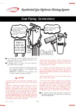
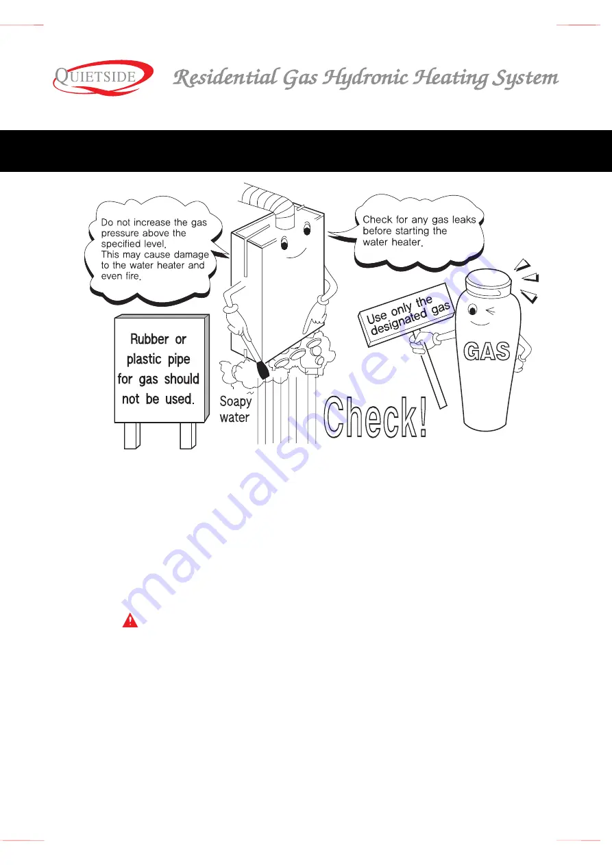
■ Use metal pipe or metal flexible pipe which has
been approved for use with gas and be sure to
install the shut off valve.
■ If propane gas is in used, the care should be
exercised for the following:
- Use a household regulator for propane gas with
the capacity matching to the indicated gas
consumption of the unit.
- Install two or more 110 lbs propane gas
cylinder (manifold cylinders together).
WARNING
This water heater is not intended to operate at gas
supply pressures other than those shown on the rating
plate.
Exposure to higher gas supply pressure may cause
damage to gas valves, which can result in fire or
explosion. If overpressure has occurred, such as through
improper testing of gas lines or emergency malfunction
of the supply system, the gas valves must be checked
for safe operation. Make sure that the outside vents on
the supply regulators and the safety vent valves are
protected against blockage. These are parts of the gas
supply system, not the water heater. Vent blockage may
occur during ice build-up or snow storms.
When local codes require a main manual shut-off
valve outside the water heater jacket, a suitable main
manual shut-off valve must be installed in a location
complying with those codes.
It is important to guard against gas valve fouling
from contaminants in the gas piping. Such fouling
may cause improper operation, fire or explosion. If
copper supply lines are used they must be approved
for gas service.
Before attaching the gas line be sure that all gas
pipe is clean on the inside.
To trap any dirt or foreign material in the gas supply
line, a dirt leg (sometimes called drip leg) must be
incorporated in the piping. The dirt leg must be readily
accessible and not subject to freezing conditions.
Install in accordance with recommendations of gas
supplier. Refer to national fuel gas code, ANSI Z223.1
or CAN/CGA-B149.1 or B149.2 (most recent edition).
■
Gas piping for water heater should be connected to
the main gas line and should not be shared by
other gas appliances.
Gas Piping Connections
Summary of Contents for QVM9 Series
Page 4: ...QVM 9 Series 2 Model QVM 9 090W1 NG 125W1 NG 150W1 NG Identifying the Components...
Page 22: ...QVM 9 Series 20 Schematic of SCF 9 Installation Installation of the Flue...
Page 26: ...QVM 9 Series 24 Thermostat Model FR 5 Using the Thermostat FR 5...
Page 39: ...37 QVM 9 Series Wiring Diagram...
Page 41: ...39 QVM 9 Series Models QVM9 090W1 NG 125W1 NG 150W1 NG Exploded Views...


