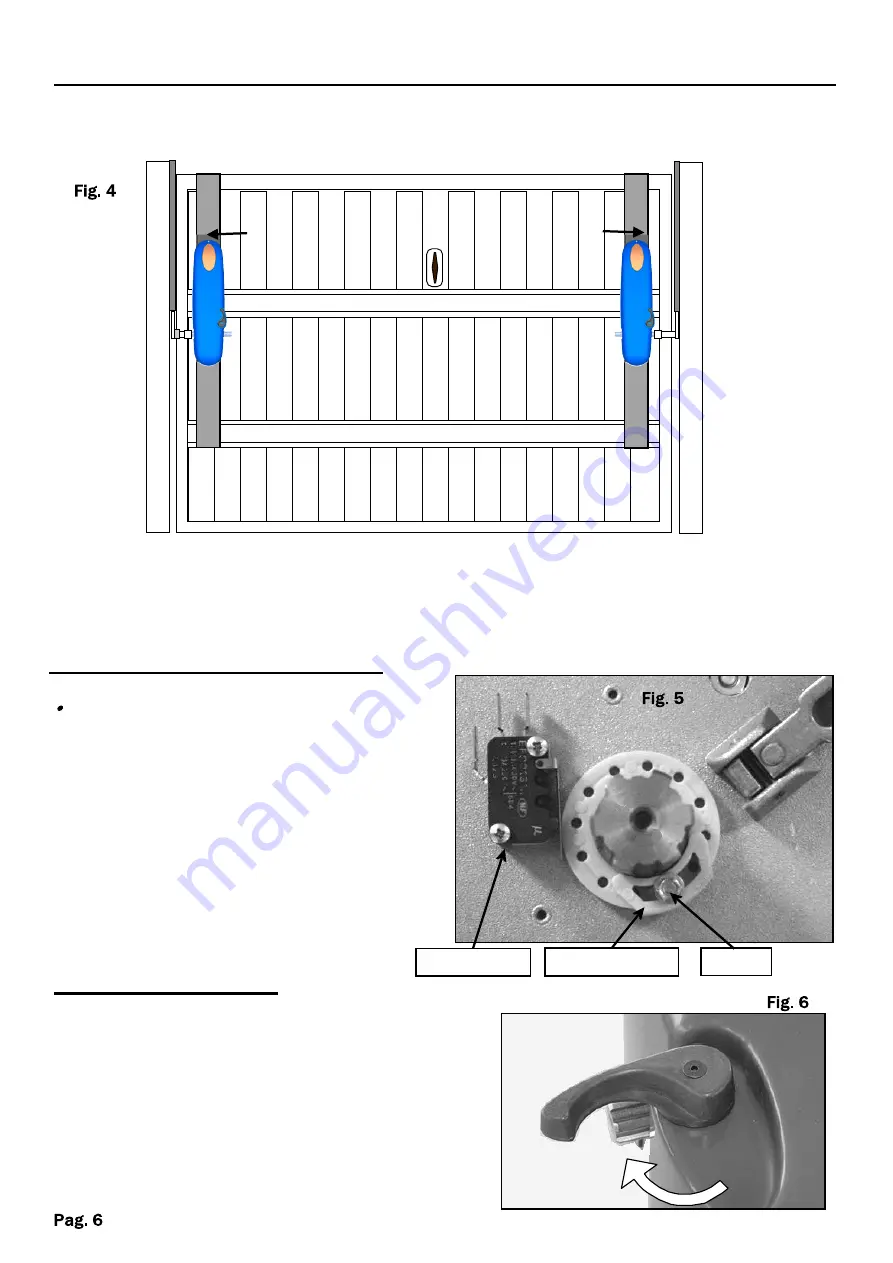
L2
L1
Limit switch C
Microswitch
Screw
M1
M2
Place and fix the motors on the fixing plates so that they are in line with the broaching
arms at a distance between
50
and
100
mm downwards by taking as reference the
attachment pin of the existing arm
(fig 2)
. Insert the broaching arms (straight or
curved) on the motor shaft and lock it.
Place the fixing plates
L
motor support to the door as illustrated.
EXAMPLE AUTOMATION TWO MOTORS WITH LATERAL INSTALLATION
INSTALLATION OF THE LATERAL FIXING PLATES
LIMIT SWITCH ADJUSTMENT
Close the door.
Ÿ
Place the limit switch
(C)
in order
to touch the lever of the
microswitch of the closing limit
switch and tigthen the screw.
·
Open the door.
Ÿ
Place the limit switch
(C)
in order
to touch the lever of the
microswitch of the opening limit
switch and tigthen the screw
.
(See also the specifications of the
control panel)
MANUAL RELEASE
In case of lack of electric power, the
motor can be manually unlocked with the
lever by performing a rotation of about
90°. T o block bring back the release lever
to its original position.
Apply the external lock
(OPTIONAL)
to
unlock the motor from the outside in case
of power failure.


