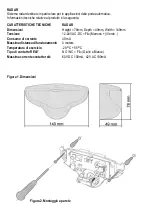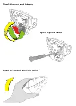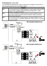
SETTING
FUNCTION
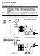
With jumper linking pins
1 ve 2
, RADAR output contacts are
NO (Normally Open)
. In
this case if motion is not detected BLUE LED is off. When motion is detected and
RADAR output is active BLUE LED becomes on.
With jumper linking pins
2
RADAR output contacts are
NC (Normally Closed)
. In this
case if motion is not detected BLUE LED is on. When motion is detected and RADAR
output is active BLUE LED becomes off.
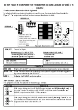
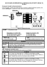
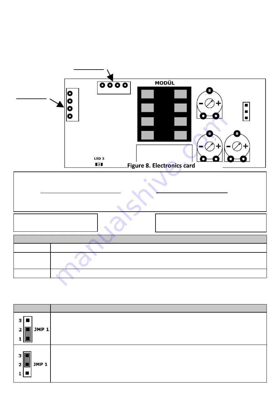
DO NOT TOUCH THE COMPONENT ON THE ELECTRONICS CARD LABELED AS “MODÜL” IN
FIGURE 8
Terminal connections and technical alignment
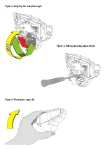
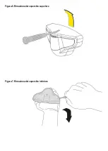
In order to adjust the controls on the electronics card, remove the upper plastic lid as illustrated in
Figure 7.
The components and their functions are described below in detail.
JMP1 OUTPUT CONTACT SETTING
This jumper determines the operation of RADAR output contact:
FUNCTION
RED LED
Flashes ON and OFF upon reception of a signal complying with your specifications
BLUE LED
Turns ON and activates the contact upon reception of a signal sufficient to trigger the
system as indicated by the RED LED.
LED 3
Indicates that RADAR card is operating.
JMP 1
output contact setting N.O. o N.C.
LED GROUPS
There are 3 LEDs on RADAR:
Power suppy ,12 - 24V AC / DC.
-A= Brown power wire po
-B= Green power wire negative -
Output contact N.O. or N.C.
-C= Yellow wire
-D= White wire
SOKET 1
Consist of 4 pin:
A
B
C
D
S
O
K
E
T
1
A B C D
SOKET 1
VERSION 1
VERSION 2
POT 1
POT 2
POT 3
3
2
1
JMP 1
CONSIST OF 4 PIN
POWER SUPPLY
brown power wire po
green power wire negative -
yellow wire
white wire


