Section V - Operating Instructions
Auto Start/Stop Pilot Valve Operation
The pilot valve is factory set to each user’s
requirement. Only adjust settings if the
requirement was unknown at time of order
or if shop air pressure differs enough from
factory preset to cause the DEFENDER™
to not function properly.
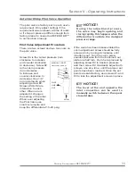
Pilot Valve Adjustment Procedure
There are two screws and two lock nuts on
the pilot valve.
Screw #4 is the cutout pressure (turn
clockwise to increase
and counter clockwise
to decrease). Screw #2
is the cut-in pressure
(turn clockwise
to increase and
counter clockwise to
decrease). Use 1/8”
turn increments when
adjusting screw #2.
Screws #4 & #2 are
interactive to each
other. When one is
adjusted it changes
the setting of the other.
When ever adjusting
the Pilot Valve use
small increments and
keep the differential at 15-20 psig.
NOTICE!
During the adjustment process,
the valve may begin opening and
closing rapidly, this happens when the
differential is outside the designed
pressure range.
If the valve has been disassembled the
cut-in adjustment screw should be fully
screwed in by turning it clockwise until
it bottoms out. Turn the cut-in screw
counterclockwise from the bottomed out
state one half turn. From here proceed by
adjusting screw #4 to desired pressure
and then screw #2. Gradually adjust both
screws, one at a time, until the proper set
points have been reached. Once the set
points are satisfactory, use screws #1 and
#3 to lock the adjustment screws in place.
NOTICE!
The lever at the end opposite the
inlet connection can be used to
manually switch between the open/
closed states.
4
3
2
1
MANUAL
LOAD
/
UNLOAD
LEVER
PILOT
LINE
OUT
AIR
IN
Quincy Compressor-DEFENDER™
11


