background image

Section IV - Installation

Installation Instructions

The Quincy DEFENDER™ nitrogen 

generator is designed for ease of 

installation.  Since it is a packaged system, 

a single-point air inlet, condensate drain, 

and an outlet connection for nitrogen gas 

(N2 out) need to made before the unit can 

be placed into operation (see below for 

connection sizes). The nitrogen generator 

is mounted on a vertical tank or can be wall 

mounted and piped to a receiver tank. 

Location & Setting of Unit

The unit should be installed indoors on 

a level surface capable of supporting the 

static weight of the equipment (with 80 gal. 

tank is approx. 305 lbs.).  The tank should 

be anchored to the floor.   The unit should 

be installed in a well-ventilated area where 

the ambient temperature range will be 

between 70° and 104°F (21°-40°C).

Inlet Air Quality

Compressed air should be supplied to 

the unit with the air dried to a dew point 

temperature lower than the expected 

minimum ambient temperature. Typical dew 

point from a properly sized refrigerated air 

dryer is sufficient (+40°F / 4°C). No water 

in liquid form should be present.  Inlet 

air pressure must be 200 psig or less. 

An advanced system of oil and particle 

removing filtration is included in the 

nitrogen generator, so pre-filtration is not 

required.

Condensate Drain Connections

A bulkhead connection is provided on the 

bottom of the panel to connect to the floor 

drain or other disposal methods to pipe 

away oily condensate from the system.  

Please note that it is normal to find oil in the 

condensate when feed compressor source 

is of the lubricated type.  (Refer to Safety 

- Environmental.)  Do not install any valves 

past the drain bulkhead.

Nitrogen Piping Connections

The final nitrogen connection is made into 

a bulkhead connection on the top of the 

panel.  No other check valves are required 

or recommended beyond this point. 

Compressed Air Inlet Connection

An NPT connection is provided for the feed 

air inlet (see below for connection sizes). 

For systems without an Auto Start/Stop it 

is recommended that an isolation valve be 

installed at the inlet of the unit. This must 

be a gate valve or other slow-opening 

valve. On such units, opening the valve 

too quickly can cause a rupture of the filter 

elements due to rapid pressurization.  Unit 

failure as a result of an improper valve or 

its use are not covered under the warranty.

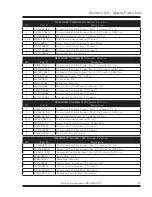
Connection Sizes

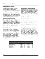
DEFENDER™ Model Feed Air Inlet Outlet Connection

N2GEN 25-70

¼” NPT

¼” NPT

N2GEN 270-520

½“ NPT 

¼” NPT

N2GEN 870

½“ NPT 

½“ NPT 

N2GEN 1800

1“ NPT

½“ NPT 

Quincy Compressor-DEFENDER™
Summary of Contents for DEFENDER 7-2716 SCFH

Page 1: ...tant safety information and should be made available to all personnel who operate and or maintain this product Carefully read this manual before attempting to operate or perform maintenance on this eq...

Page 2: ......

Page 3: ...densate Drain Connections 8 Nitrogen Piping Connections 8 Compressed Air Inlet Connection 8 Pre start Inspection 9 Initial Start up Adjustment 9 Nitrogen Purity Sampling Setup 9 Section V Operating In...

Page 4: ......

Page 5: ...in minor personal injury or property damage NOTICE Identifies important installation operation or maintenance information which is not hazard related DANGER This symbol identifies immediate hazards w...

Page 6: ...s manual before attempting to operate the unit Although this unit is very simple to operate the user will be working with high pressure gas that must be handled with caution DANGER Compressed gas if h...

Page 7: ...o not substantially fulfill performance requirements set forth in the Company literature and are manufactured in accordance with the Company s s p e c i f i c a t i o n s o r g o v e r n m e n t speci...

Page 8: ...arbon carryover at or below 2 parts per billion Nitrogen System Description Inside the DEFENDER nitrogen generator the compressed air rst comes into contact with the membrane pre ltration system On St...

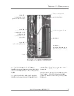
Page 9: ...he analyzer Two pressure gauges are installed on the front panel One is for displaying inlet pressure and the other for system outlet pressure Example of a QUINCY DEFENDER FILTER 3 ACTIVATED CARBON FI...

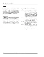
Page 10: ...depleted levels of oxygen is given below Effects Symptoms of Decreased oxygen Levels 15 19 Decreased ability to work s t r e n u o u s l y M a y i m p a i r coordination and may induce early symptoms...

Page 11: ...he presence of oxygen rich air It is imperative that vented gas be discharged only in safe well ventilated areas If the unit is located in a poorly ventilated room the waste gas must be piped to a ven...

Page 12: ...il and particle removing ltration is included in the nitrogen generator so pre ltration is not required Condensate Drain Connections A bulkhead connection is provided on the bottom of the panel to con...

Page 13: ...re pressurize after each purge The nitrogen can be delivered to the system after the initial purging procedure Nitrogen Purity Sampling Setup 1 If the unit is equipped with the built in analyzer make...

Page 14: ...t isolation valve and perform the purge process again If the tank remains pressurized during downtime weekends holidays etc this step is not required 3 Go Online After venting the system is ready to u...

Page 15: ...ver adjusting the Pilot Valve use small increments and keep the differential at 15 20 psig NOTICE During the adjustment process the valve may begin opening and closing rapidly this happens when the di...

Page 16: ...wn at time of order NOTICE If the purity is not at or better than required and the pressure and temperature going into the system are as required the Flow Purity Controller can be adjusted to meet the...

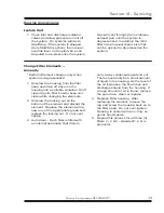
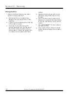
Page 17: ...Stuff clean rag into lter bowl to keep unit clean while changing the elements 2 Unscrew the locking nut on the bottom of the element and discard the element Replace the element with a new one of the...

Page 18: ...rom the top end of the carbon vessel to allow access to the carbon Drain the carbon into a container and replace with fresh carbon d Replace Hex bushing with screen attached using Te on tape on the th...

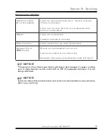
Page 19: ...PERATION OF ALL SAFETY RELIEF VALVES ANNUALLY OR AT 8000 HOURS REPLACE ALL FILTER ELEMENTS ON THE UNIT CHANGE THE CARBON IN THE CARBON BED ANALYZER S SENSOR WILL NEED REPLACING EVERY 2 3 YEARS NOTICE...

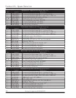
Page 20: ...1 CXNT 00030 COALESCING PRE FILTER NO 2 COMPLETE 1 ACNT 00030 ADSORBING PRE FILTER NO 3 COMPLETE DEFENDER N2GEN 270 520 PREMIUM FILTRATION QTY PART DESCRIPTION 1 CSNE 00030 COALESCING PRE FILTER ELEME...

Page 21: ...PRE FILTER NO 1 COMPLETE 1 CXNT 00060 COALESCING PRE FILTER NO 2 COMPLETE 1 ACNT 00060 ADSORBING PRE FILTER NO 3 COMPLETE DEFENDER N2GEN 1800 PREMIUM FILTRATION QTY PART DESCRIPTION 1 CSNE 00150 COALE...

Page 22: ...isk and storage charges may be applied at the discretion of Seller Accounts past due shall bare interest at the highest rate lawful to contract for but if there is no limit set by law such interest sh...

Page 23: ...d to seller freight prepaid for inspection Seller warrants repaired or replaced parts of its own manufacture against defects in materials and workmanship under normal use and service for ninety 90 day...

Page 24: ..._____________________________________________________ ____________________________________________________________________ ____________________________________________________________________ ________...

Page 25: ......

Page 26: ...te Alabama 36507 Phone 251 937 5900 Fax 251 937 1457 Nearest Distributor 888 424 7729 E mail info quincycompressor com The Science of Compressed Air quincycompressor com 2005 Quincy Compressor an EnPr...

Reviews: