Installation
Area of Installation
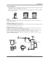
• Sealed floor or collecting basin. It is crucial to ensure that untreated condensate or oil cannot
get into the sewer system in the event of damage.
• The floor area must be stable and level (max. inclination 1°) to ensure reliable functioning of the
EWS.
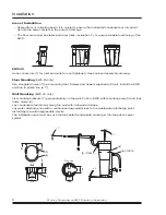
EWS 20
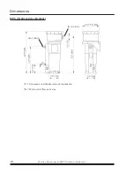
Hose connectors (1) for inlet and outlet are not tightened. See enclosed assembly drawing.
Floor Mounting
(EWS 20 only)
Use elongated holes of the 4 mounting feet. Screws and dowels supplied with unit. Install the EWS
unit true to plumb line (± 1°).
Wall Mounting
(EWS 20 only)
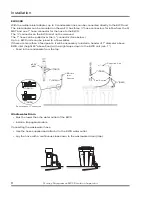
Fix mounting brackets (7) perpendicularly on the wall. Push in EWS with mounting area (9) and lock
home clamp (8).
Lay condensate feed line(s) along the wall with a downward slope.
Lay water discharge line with a continuous downward slope to the wastewater discharge point.
Install trap to avoid disagreeable smells.
The installation area must be such that untreated condensate cannot get into the public sewer
system.
6.7”
(170)
0.8” (20)
3.5”
(90)
3.9”
(100)
A
A
A-A
3.9”
(100)
3.9”
(100)
± 1°
± 1°
> 1°
(9)
(1)
½"(DN13)
(4)
½"(DN13)
(7)
(8)
7
S
IDE
VIEW
6
Quincy Compressor-EWS Emulsion Separator


