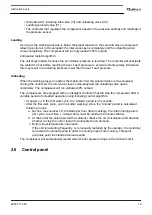
• Unloader (UA), including inlet valve (IV) and unloading valve (UV).
• Loading solenoid valve (Y1).
• The controller that regulates the compressor based on the pressure settings and readings of
the pressure sensor.
Loading
As long as the working pressure is below the preset maximum, the solenoid valve is energised,
allowing control air to the unloader: the inlet valve opens completely and the unloading valve
closes completely. The compressor will run fully loaded (100% output).
Anticipated restart algorithm:
The unit stops loaded, because the set ‘Unload’ pressure is reached. The controller will anticipate
the restart 0,2 bar before reaching the set ‘Load’ pressure to avoid a restarting delay. Otherwise
this may result in a restarting pressure lower than the set ‘Load’ pressure.
Unloading
When the working pressure reaches the maximum limit, the solenoid valve is de-energised,
venting the control air: the inlet valve closes completely and the unloading valve opens
completely. The compressor will run unloaded (0% output).
The compressors are equipped with an intelligent controller that will stop the compressor after a
variable period of unloaded operation using following control algorithm:
• At power on, in the first work cycle, the ‘Unload’ period is 30 seconds.
• After the first work cycle, and in all other working cycles, the ‘Unload’ period is calculated
following 3 rules:
a. Given a max number of 10 restarts per hour (factory setting), the total running period
per cycle (‘Load’ time + ‘Unload’ time) must be minimum 6 minutes (360s).
b. At the end of the unload period the controller checks the air consumption and decides
whether to stop the unit or restart to anticipate the air demand.
c. Motor virtual temperature calculation.
If the unit is restarting frequently, or is manually restarted by the operator, the controller
will extend the unload period in order to ensure proper motor cooling. This point
overrules point the standard unload period.
The compressor will automatically restart when the net pressure drops to the minimum limit.
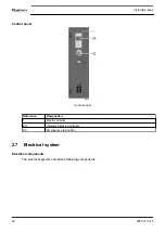
2.6
Control panel
Instruction book
2920 7113 40
19
Summary of Contents for QGS 10
Page 1: ...Quincy Oil injected rotary screw compressors QGS 10 QGS 15 QGS 20S Instruction book ...
Page 2: ......
Page 18: ...2 3 Oil system Oil system Oil system units with dryer Instruction book 16 2920 7113 40 ...
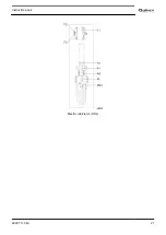
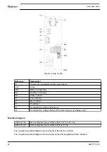
Page 23: ...Electric cubicle UL DOL Instruction book 2920 7113 40 21 ...
Page 51: ...208 230 460V 60Hz Instruction book 2920 7113 40 49 ...
Page 68: ...The new service interval is now set Instruction book 66 2920 7113 40 ...
Page 74: ...Line filters Instruction book 72 2920 7113 40 ...
Page 84: ...8 Problem solving Control panel Air outlet valve Instruction book 82 2920 7113 40 ...
Page 85: ...Oil filler plug Condensate drain valve on air receiver Instruction book 2920 7113 40 83 ...
Page 94: ......
Page 95: ......


