background image

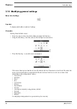
3.16 Modifying general settings

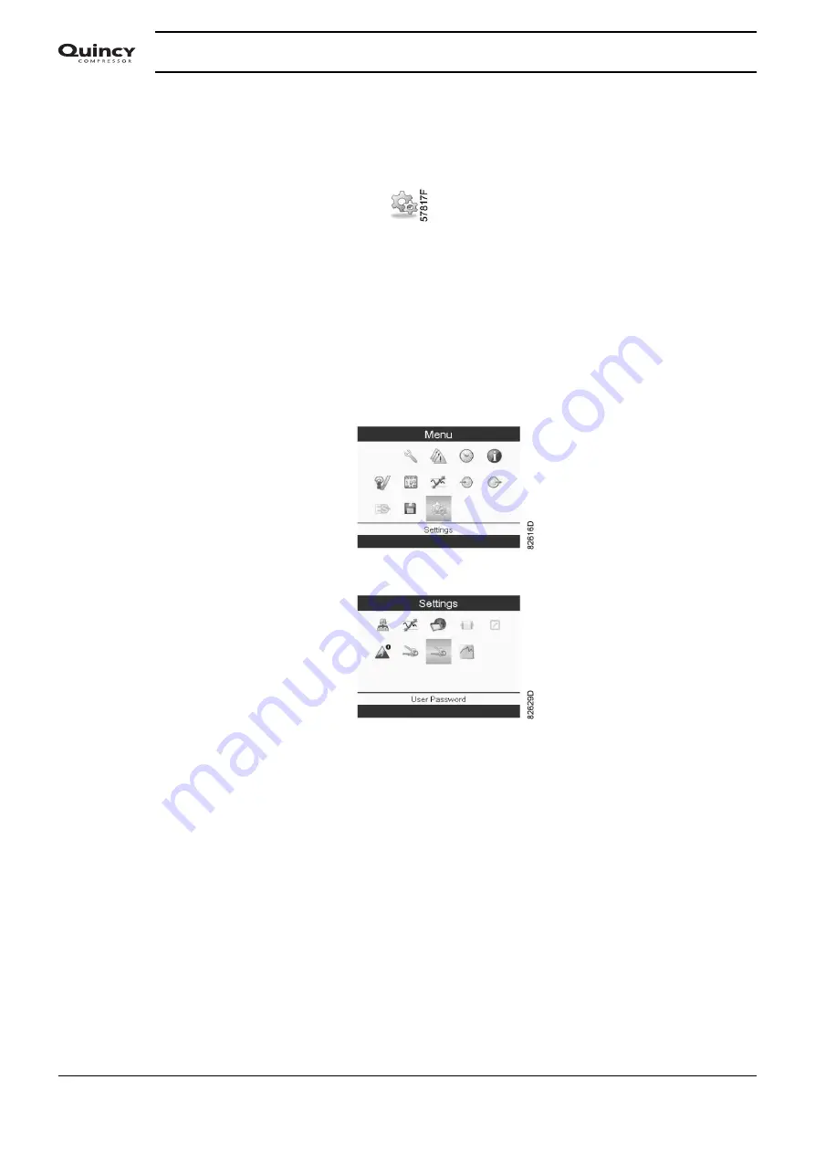
Menu icon, Settings

Function

To display and modify a number of settings.

Procedure

Starting from the Main screen,

• Move the cursor to the action button Menu and press the Enter key.
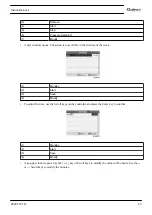
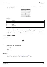
• Using the Scroll keys, move the cursor to the Settings icon (see below).

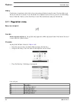
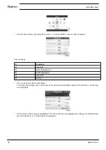
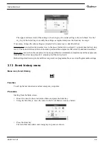
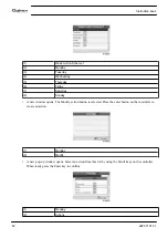
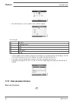
• Press the Enter key. A second menu screen appears:

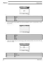
This screen shows again a number of icons. By default, the User Password icon is selected. The status bar
shows the description that corresponds with the selected icon. Each icon covers one or more items
(depending on the configuration), such as
• Access level
• Elements
• Dryer
• Fan
• Converter(s)
• Filter(s)
• Motor/Starter
• General
• Automatic restart after voltage failure (ARAF)
• Network
• Regulation
• Remote
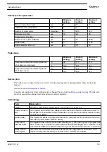
For adapting certain parameters, a password may be necessary.

Instruction book

50

2920 7101 21

Summary of Contents for QGS 40

Page 1: ...QGS 40 QGS 50 QGS 60 QGS 75 QGS 100 Instruction book Oil flooded rotary screw compressors...

Page 2: ......

Page 3: ...s valid for CE as well as non CE labelled machines It meets the requirements for instructions specified by the applicable European directives as identified in the Declaration of Conformity Quincy Comp...

Page 4: ...INTRODUCTION 10 2 2 AIR AND OIL CIRCUIT 12 2 3 REGULATING SYSTEM 14 2 4 ELECTRICAL SYSTEM 15 3 Graphic controller 17 3 1 CONTROLLER 17 3 2 CONTROL PANEL 18 3 3 ICONS USED 19 3 4 MAIN SCREEN 23 3 5 CA...

Page 5: ...rating instructions 63 5 1 INITIAL START UP 63 5 2 BEFORE STARTING 66 5 3 STARTING 66 5 4 DURING OPERATION 67 5 5 AUTOMATIC RESTARTING 69 5 6 STOPPING 69 5 7 TAKING OUT OF OPERATION 70 6 Maintenance 7...

Page 6: ...IONS AND LIMITATIONS 88 9 3 COMPRESSOR DATA 88 10 Options 90 10 1 AUTOMATIC DRAIN 90 10 2 HEAVY DUTY FILTER 91 10 3 PRE FILTRATION PANELS 91 10 4 ROTATION DIRECTION INDICATOR PHASE CONTROLLER 93 10 5...

Page 7: ...ompressor press the emergency stop button switch off the voltage and depressurize the compressor In addition the power isolating switch must be opened and locked On units powered by a frequency conver...

Page 8: ...ed on the air outlet valve the connected pipe must be free of strain 10 If remote control is installed the machine must bear a clear sign stating DANGER This machine is remotely controlled and may sta...

Page 9: ...olled machines shall take adequate precautions to ensure that there is no one checking or working on the machine To this end a suitable notice shall be affixed to the remote start equipment 4 Never op...

Page 10: ...tached to the starting equipment 6 Persons switching on remotely controlled machines shall take adequate precautions to ensure that there is no one checking or working on the machine To this end a sui...

Page 11: ...ssure level from increasing 20 Never use caustic solvents which can damage materials of the air net e g polycarbonate bowls 21 The following safety precautions are stressed when handling refrigerant N...

Page 12: ...lable in air cooled version The compressors are enclosed in sound insulated bodywork The compressors are controlled by the AIRLOGIC controller The AIRLOGIC controller and the emergency stop button are...

Page 13: ...ponents Ref Name AF Air filter AR Air receiver AV Location of air outlet valve Ca Air cooler Co Oil cooler ER Controller M1 Drive motor OF Oil filter S3 Emergency stop button Instruction book 2920 710...

Page 14: ...The air is discharged through outlet valve AV via minimum pressure valve Vp and air cooler Ca During loaded operation minimum pressure valve Vp keeps the pressure in the separator tank AR above a min...

Page 15: ...valve BV shuts off the supply to oil cooler Co and the oil cooler is bypassed Air pressure forces the oil from air receiver oil separator AR through oil filter OF and oil stop valve Vs to compressor...

Page 16: ...rol pressure present in the chambers of loading plunger LP and unloading valve UV is vented to atmosphere via solenoid valve Y1 Loading plunger LP moves upwards and causes inlet valve IV to close the...

Page 17: ...ia solenoid valve Y1 to loading plunger LP and unloading valve UV Unloading valve UV closes the air blow off opening Loading plunger LP moves downwards and causes inlet valve IV to open fully Air deli...

Page 18: ...d F21 Overload relay compressor motor Q15 Circuit breaker fan motor on air cooled compressors K21 Line contactor K22 Star contactor K23 Delta contactor T1 Transformer X103 X108 Connectors PE Earth ter...

Page 19: ...or compressors with frequency converter the minimum stop time and the maximum number of motor starts and several other parameters are taken into account The controller stops the compressor whenever po...

Page 20: ...d to warn the operator before the shut down level is reached Service warning If the service timer exceeds a programmed value this will be indicated on the display to warn the operator to carry out som...

Page 21: ...bol 9 LED Service Is lit when service is needed 10 Start button This button starts the compressor Automatic operation LED 3 lights up The controller is operative 11 Stop button This button is used to...

Page 22: ...tage failure Automatic restart after voltage failure is active Week timer Week timer is active Active protection functions Emergency stop Shutdown Warning Service Service required Main screen display...

Page 23: ...on Description Pressure Temperature Digital input Special protection System icons Icon Description Compressor element LP HP Dryer Fan Frequency converter Drain Filter Motor Failure expansion module Ne...

Page 24: ...ns Icon Description Inputs Outputs Protections Warnings shutdowns Counters Test Regulation Settings Service Event history saved data Access key User password Network Setpoint Information Week Timer Ge...

Page 25: ...d Typically 5 different main screen views can be chosen 1 Two value lines 2 Four value lines 3 Chart High resolution 4 Chart Medium resolution 5 Chart Low resolution Two and four value lines screens T...

Page 26: ...A shows information regarding the compressor operation e g the outlet pressure or the temperature at the compressor outlet On compressors with a frequency converter the load degree flow is given in o...

Page 27: ...a timer or message To activate an action button highlight the button by using the Scroll keys and press the Enter key To go back to the previous menu press the Escape key Chart views Instead of viewi...

Page 28: ...ut required and press the Enter key See also section Inputs menu 3 5 Calling up menus Description When the voltage is switched on the main screen is shown automatically To go to the Menu screen highli...

Page 29: ...as shown in the following screen Press the Enter key A screen similar to the one below appears Text on image 1 Inputs 2 Compressor outlet 3 Element outlet 4 Ambient air 5 Emergency stop The screen sh...

Page 30: ...tem in the list is highlighted In this example the Net Pressure is selected chart icon To change press the Enter button again a pop up window opens Press Enter again to remove this input from the char...

Page 31: ...on of the Fan overload contact on air cooled compressors the Emergency stop contact etc Procedure Starting from the Main screen Move the cursor to the action button Menu and press the Enter key Move t...

Page 32: ...icon respectively 3 8 Counters Menu icon Counters Function To call up The running hours The loaded hours The number of motor starts The number of hours that the regulator has been powered The number o...

Page 33: ...compressor the actual screen will be somewhat different 3 9 Control mode selection Function To select the control mode i e whether the compressor is in local control remote control or controlled via a...

Page 34: ...of the icons 3 10 Service menu Menu icon Service Function To reset the service plans which are carried out To check when the next service plans are to be carried out To find out which service plans we...

Page 35: ...Overview 3 Service plan 4 Next service 5 History Scroll through the items to select the desired item and press the Enter key to see the details as explained below Overview Text on image 1 Overview 2 R...

Page 36: ...till has 4000 running hours or 8299 hours to go before the next Service intervention Service plans A number of service operations are grouped called Level A Level B etc Each level stands for a number...

Page 37: ...nfirm Note Running hours can be modified in steps of 100 hours real time hours can be modified in steps of 1 hour Next Service Text on image 1 Next service 2 Level 3 Running hours 4 Actual In the exam...

Page 38: ...icon Setpoint Function On fixed speed compressors the operator can program two different pressure bands This menu is also used to select the active pressure band Procedure Starting from the Main scre...

Page 39: ...ng is shown in black Use the or key of the Scroll keys to modify the settings as required and press the Enter key to accept If necessary change the other settings as required in the same way as descri...

Page 40: ...el 1 5 Setpoint 2 6 Modify The screen shows the actual settings To modify the settings move the cursor to the action button Modify and press the Enter key Following screen appears The first line of th...

Page 41: ...ion Direct stop occurs when the compressor runs at a speed between minimum and maximum and the net pressure rises above the direct stop setpoint setpoint plus Direct stop level Both settings Indirect...

Page 42: ...op commands for the compressor To program time based change over commands for the net pressure band Four different week schemes can be programmed A week cycle can be programmed a week cycle is a seque...

Page 43: ...t Week action schemes and press Enter A new window opens The first item in the list is highlighted in red Press the Enter key on the controller to modify Week Action Scheme 1 1 Week Action Schemes 2 W...

Page 44: ...s The Modify action button is selected Press the enter button on the controller to create an action 1 Monday 2 Modify A new pop up window opens Select an action from this list by using the Scroll keys...

Page 45: ...eek 1 Monday 2 Start 3 Save 4 Modify To adjust the time use the Scroll keys on the controller and press the Enter key to confirm 1 Monday 2 Start 3 Save 4 Modify A pop up window opens Use the or key o...

Page 46: ...on Modify is selected Use the Scroll keys to select the action Save 1 Monday 2 Start 3 Save 4 Modify A new pop up window opens Use the Scroll keys on the controller to select the correct actions Press...

Page 47: ...ursday 6 Friday 7 Saturday 8 Sunday Press the Escape key on the controller to leave this screen Programming the week cycle A week cycle is a sequence of 10 weeks For each week in the cycle one of the...

Page 48: ...ler to modify the first week A new window opens Select the action example Week Action Scheme 1 1 Week Cycle 2 Week 1 3 Week Action Scheme 1 4 Week Action Scheme 2 5 Week Action Scheme 3 6 Modify Check...

Page 49: ...tive 6 Remaining Running Time A new window opens Select Week 1 to set the Week Timer active 1 Week Timer 2 Week 3 Week Timer Inactive 4 Week 1 Press the Escape key on the controller to leave this wind...

Page 50: ...Enter key on the controller to Modify 1 Week Timer 2 Week Action Schemes 3 Week Cycle 4 Status 5 Remaining Running Time This timer is used when the week timer is set and for certain reasons the compr...

Page 51: ...the scroll keys move the cursor to the Test icon see below Press the Enter key following screen appears Text on image 1 Test 2 Safety Valve Test 3 Not allowed 4 Audit Date The safety valve test can on...

Page 52: ...cond menu screen appears This screen shows again a number of icons By default the User Password icon is selected The status bar shows the description that corresponds with the selected icon Each icon...

Page 53: ...rst item Language is highlighted Use the key of the Scroll keys to select the setting to be modified and press the Enter key A pop up screen appears Use the or key to select the required value and pre...

Page 54: ...bar is covering the first item Language Use the key of the Scroll keys to select the setting to be modified and press the Enter key To modify select the Modify button using the Scroll keys and press...

Page 55: ...ying general settings Using the Scroll keys move the cursor to the User Password icon see below Press the Enter key Next screen appears Select the Activate button and press the Enter key Next fill in...

Page 56: ...below Three Access levels are possible 0 A basic set of parameters is visualized no password is required 1 A basic set of parameters can be modified 2 Extra parameters will be visualized and can be mo...

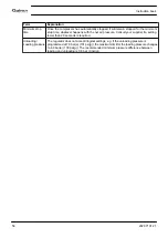
Page 57: ...The intervals must not exceed the nominal intervals and must coincide logically Terminology Term Explanation ARAVF Automatic restart after voltage failure See section Controller and Power recovery ti...

Page 58: ...er if a setting lower than 20 seconds is required Unloading Loading pressure The regulator does not accept illogical settings e g if the unloading pressure is programmed at 7 0 bar e 101 psi g the max...

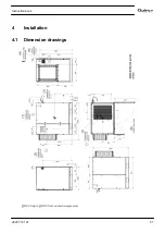
Page 59: ...4 Installation 4 1 Dimension drawings QGS 40 up to QGS 60 air cooled compressors Instruction book 2920 7101 21 57...

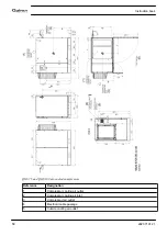
Page 60: ...ir cooled compressors Reference Designation 1 Compressor cooling air outlet 2 Compressor cooling air inlet 3 Compressed air outlet 4 Electrical cable passage 5 Cubicle cooling air outlet Instruction b...

Page 61: ...oved by a lift truck using the slots in the frame Take care not to damage the bodywork during lifting or transport Make sure that the forks protrude from the other side of the frame The compressor can...

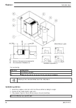
Page 62: ...ng to be connected stress free to the compressor Installation guidelines 1 Install the compressor unit on a solid level floor suitable for taking its weight 2 Position of the compressed air outlet val...

Page 63: ...lector Any flow back must be avoided Oil water separators to separate the major part of the oil from the condensate to ensure that the condensate meets the requirements of the environmental codes are...

Page 64: ...e 6 Earth connection 7 Take care of voltage wait 6 min before removing panel 8 Warning Automatic start read the instruction manual no service with voltage and pressure on 9 Before connecting compresso...

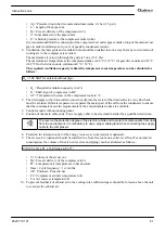
Page 65: ...ure For the position of the air outlet valve and the drain connections see sections Introduction 1 Consult the sections Electric cable size Installation proposal and Dimension drawings 2 The following...

Page 66: ...switch must be installed near the compressor 4 Check transformer T1 for correct connection Check the settings of drive motor overload relay F21 Check that the motor overload relay is set for manual re...

Page 67: ...y restart after voltage failure The compressor is automatically controlled and may be restarted automatically 9 Check the voltage between the three phases before using the unit for the first time Moto...

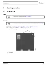
Page 68: ...to improve the lubrication of the compressor element at starting Disconnect the inlet hose remove the unloader UA and pour 0 75 l 0 20 US gal 0 17 Imp gal of oil into the compressor element Reinstall...

Page 69: ...star to delta and the compressor starts running loaded 5 4 During operation Warnings The operator must apply all relevant Safety precautions Also consult section Problem solving Removing the front pa...

Page 70: ...between the lower region and the centre in the sight glass Gl If the level is too low stop the compressor wait until the compressor has stopped depressurise the oil system by unscrewing oil filler pl...

Page 71: ...automatically restart the compressor when the voltage is restored after voltage failure Whenever the compressor is shut down the emergency push button must be pressed or the electricity isolating swi...

Page 72: ...drain s until the air system between the air system receiver and the outlet valve is fully depressurised See section Automatic drain Switch off the voltage If available open the condensate drain valve...

Page 73: ...the use of unauthorised parts is not covered by Warranty or Product Liability Service kits For overhauling or carrying out preventive maintenance service kits are available see section Service kits S...

Page 74: ...ns Interval hours 500 2000 4000 8000 10000 14000 16000 20000 22000 6000 18000 12000 24000 Operations to be carried out Visit A Visit B Visit C Visit D 1 Control measured parameters x x x x x 2 Change...

Page 75: ...eplaced 6 2 Storage after installation Procedure Run the compressor regularly e g twice a week until warm Load and unload the compressor a few times If the compressor is going to be stored without run...

Page 76: ...s running 2 For minimum downtime replace the dirty element by a new one 3 Discard the element when damaged Procedure 1 Stop the compressor Switch off the voltage 2 Release the snap clips of air filter...

Page 77: ...tank Procedure Oil system components 1 Run the compressor until warm Stop the compressor Close the air outlet valve and switch off the voltage Depressurise the compressor by opening manual drain valve...

Page 78: ...settle 8 Depressurise the system by unscrewing filler plug FC just one turn to permit any pressure in the system to escape Remove the plug Add oil the oil level should be between the lower region and...

Page 79: ...e middle of sight glass Gl 6 Run the compressor loaded for a few minutes Stop the compressor and wait a few minutes to allow the oil to settle 7 Depressurise the system by unscrewing filler plug FC ju...

Page 80: ...sure air If necessary the pressure may be increased up to 6 bar e 87 psig 7 5 Filtering panel Cleaning the filtering panel Before carrying out any operation on the machine ensure that the electric pow...

Page 81: ...ing Before removing the valve depressurise the compressor See section Problem solving Valve SV can be tested on a separate air line If the valve does not open at the set pressure stamped on the valve...

Page 82: ...sections Introduction and Initial start up Open and lock the isolating switch The operator must apply all relevant Safety precautions Position of air vent plug Compressor On compressors equipped with...

Page 83: ...ecessary Scavenge line clogged Check and remedy Condition Fault Remedy Excessive oil flow through air inlet filter after stopping compressor Check valve leaking or oil stop valve jammed Replace defect...

Page 84: ...lt Remedy Thermostatic bypass valve malfunctioning Have valve tested Air cooler clogged Clean cooler Compressor element out of order Consult your supplier Oil filter clogged Replace Instruction book 8...

Page 85: ...ed below Cable sizing according IEC The tables below indicate the current carrying capacities of cables for 3 commonly used installation methods calculated according to standard 60364 5 52 electrical...

Page 86: ...0 A 145 A 131 A 112 A 95 mm 223 A 194 A 176 A 158 A 136 A 120 mm 259 A 225 A 205 A 184 A 158 A Installation method F according table B 52 1 Single core cables touching in free air Clearance to wall no...

Page 87: ...Therefore use a 3 x 70 mm 35 mm cable If method C is used 50 mm is suffficient 35 mm for method F cable 3 x 50 mm 25 mm Parallel supply cable 2 x 3 phases PE configuration 2 I 89 A 10 2 89 x 1 1 2 49...

Page 88: ...supply cables For supply cables larger than AWG8 use maximum allowed ampacity of the selected supply cables and compare with value in table below see CEC Part 1 table 17 100 A use AWG8 200 A use AWG6...

Page 89: ...Fuse size the recommended maximum fuse size divided by 3 on each cable Size PE cable For supply cables up to AWG8 same size as the supply cables For supply cables larger than AWG8 use maximum allowed...

Page 90: ...let temperature C 46 Maximum air inlet temperature F 115 Minimum ambient temperature C 0 Minimum ambient temperature F 32 9 3 Compressor data Reference conditions All data specified below apply under...

Page 91: ...116 141 165 Loading pressure Minimum setting bar e 4 4 4 4 4 4 4 4 psig 58 58 58 58 58 58 58 58 Set point thermostatic valve C 40 40 40 65 40 40 40 65 F 104 104 104 149 104 104 104 149 Units 7 5 bar...

Page 92: ...ance The purge valve does not require the use of the metallic intake filter that is usually installed on electronic purge valves to protect the solenoid valve The solenoid valve will not be damaged Co...

Page 93: ...s depending on the model outside the compressor for intake of fresh air hence resulting in a lower oil temperature and more efficient compression 10 3 Pre filtration panels Description Installing air...

Page 94: ...enance costs Access to the filtering media is allowed by removal that does not require any particular tool The panel frame can be unlocked manually in order to clean the medium Exceptional longevity o...

Page 95: ...troller enables permanent and easier verification of the rotation direction of the machine by means of a diode This prevents any risk of physical damage by disabling the compressor start up in case of...

Page 96: ...nt oils meet different needs 4000 hours oil longer interval between 2 drainage operations 4000 hours under standard conditions of use 8000 hours oil longer interval between 2 drainage operations 8000...

Page 97: ...r the design are shown and or referred to The Declaration of Conformity Declaration by the Manufacturer is part of the documentation that is supplied with this compressor Local legal requirements and...

Page 98: ...re Vessel Directive 87 404 EEC Compressor type Component Description Volume Design pressure Minimum and maximum design temperature PED Class 30 50 kW 1631 0137 80 Vessel 41 l 15 bar e 10 C 120 C SPV 5...

Page 99: ...laration of conformity Typical example of a Declaration of Conformity document 1 Contact address Quincy Compressor 701 North Dobson Avenue Bay Minette AL 36507 United States Instruction book 2920 7101...

Page 100: ......

Page 101: ......
Page 102: ...Quincy Compressor Products 217 222 7700 E mail info quincycompressor com Website quincycompressor com 2012 Quincy Compressor All Rights Reserved Litho in U S A...

Reviews: