Instruction book
2012 2039 28
26
Close the service valve when the compressor is not being used to prevent the
system’s air pressure from leaking back into the compressor if the check valve leaks or
fails.
Emergency
Press the emergency stop button or cut the power at the main disconnect switch or panel.
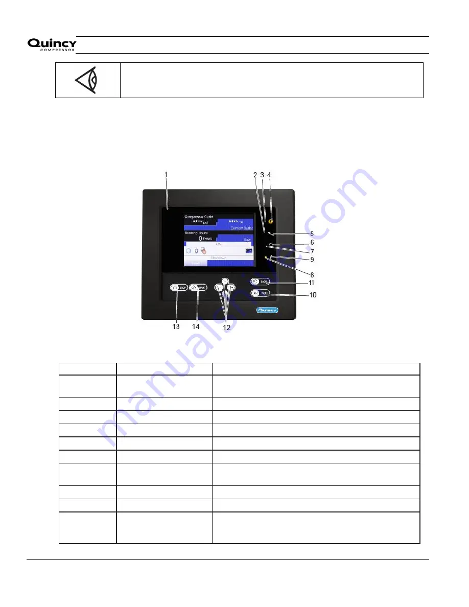
3.3 Control panel
Q control
Parts and functions
Reference
Designation
Function
1
Display
Shows the compressor operating condition and a number of
icons to navigate through the menu.
2
Service LED
Lights up if service is needed
3
General alarm LED
Flashes if a shut-down warning condition exists
4
Pictograph
General alarm
5
Pictograph
Service
6
Pictograph
Automatic operation
7
Automatic operation LED
Indicates that the regulator is automatically controlling the
compressor.
8
Voltage on LED
Indicates that the voltage is switched on.
9
Pictograph
Voltage on
10
Enter key
Key to select the parameter indicated by the horizontal
arrow. Only the parameters followed by an arrow pointing to
the right can be modified.
Summary of Contents for QGV 40
Page 2: ......
Page 16: ...Instruction book 2012 2039 28 16 Main components Main components...
Page 128: ...Instruction book 2012 2039 28 128 Appendix 1 Product Analysis Report...
Page 131: ......


