Section II - Description
Quincy Compressor
9
Text on image
(1)
Compressor module 1
(10)
Air
(2)
Compressor module 2
(11)
Drain
(3)
Compressor module 3
(12)
Mechanical link
(4)
Compressor module 4
(13)
Electrical signal
(5)
To cubicle
(14)
Electric energy
(6)
Refrigerant dryer (units with dryer)
(15)
Enclosure
(7)
Water separator (units without dryer)
(16)
Local mounting
(8)
Outlet
(17)
On control cabinet
(9)
Ambient temperature sensor
Air flow
Air is drawn through air filter (100) and is compressed by the compressor element (102)
of each compressor module. The compressed air is discharged via the check valve (104)
and a common air cooler (112).
On compressors without integrated dryer, the compressed air passes a water separator
(111) and flows to the outlet valve (121).
On standard compressors with an integrated air dryer, the compressed air flows through
a common refrigerant dryer (300) before reaching the outlet valve (121). For details on
the operation of the dryer, see section Refrigerant dryer.
Cooling
Each compressor element (102) is cooled by a radial fan (124), mounted on the drive
shaft of the compressor element. The cooling air is blown over the compressor element
via a duct.
A separate electric fan (130) provides cooling air for the common air cooler (112).
Condensate management
The water separator (111) on compressors without integrated dryer has an automatic
condensate outlet and a manual drain valve.
On compressors with integrated dryer, the dryer is equipped with a water trap with an
automatic condensate outlet and a manual drain valve.
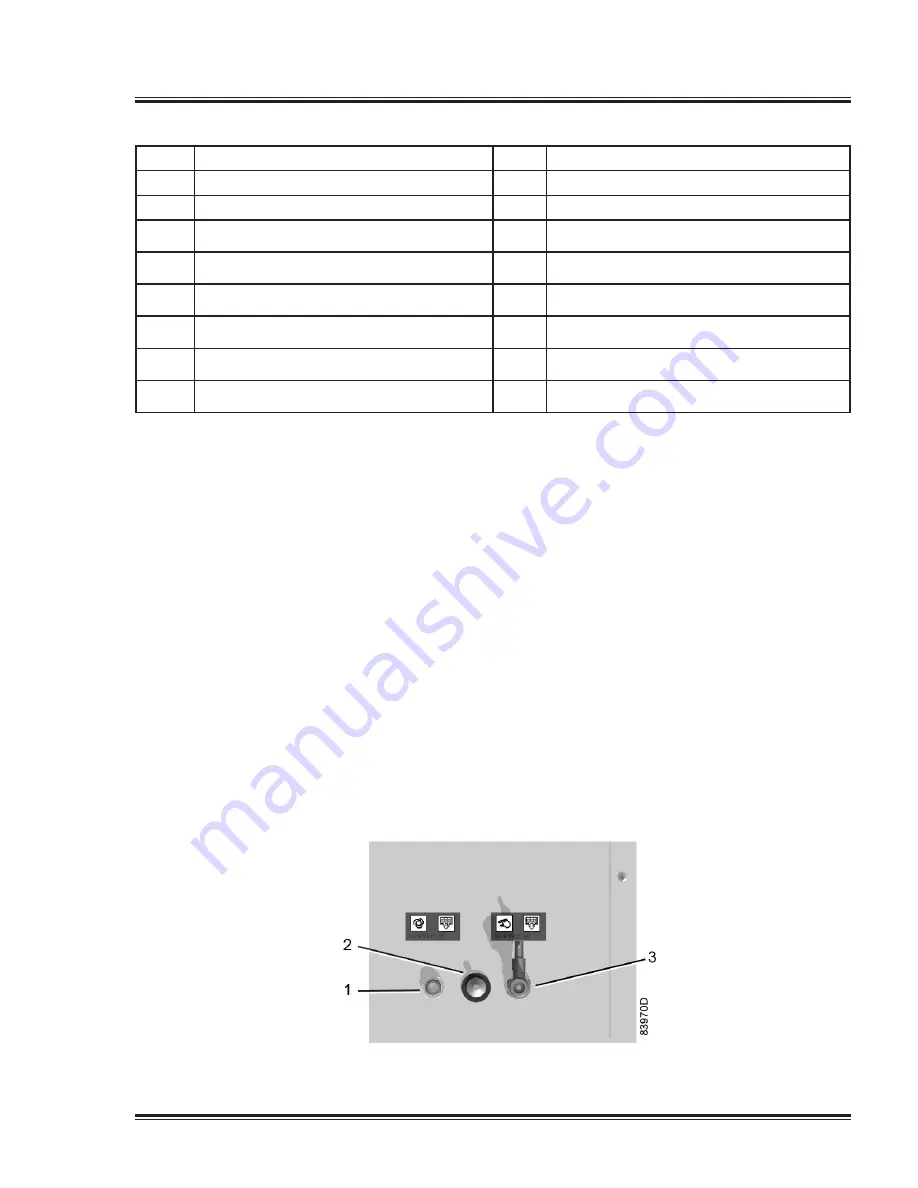
Condensate drain connections (typical)


